Internal Assemblies — Main Chassis 4: Repair
119
SpO2 PCA
Preparation
1 Open the Case. See “Opening the Case” on page 90.
2 Remove the Measurement Module. See “Measurement Module” on page 107.
Removal
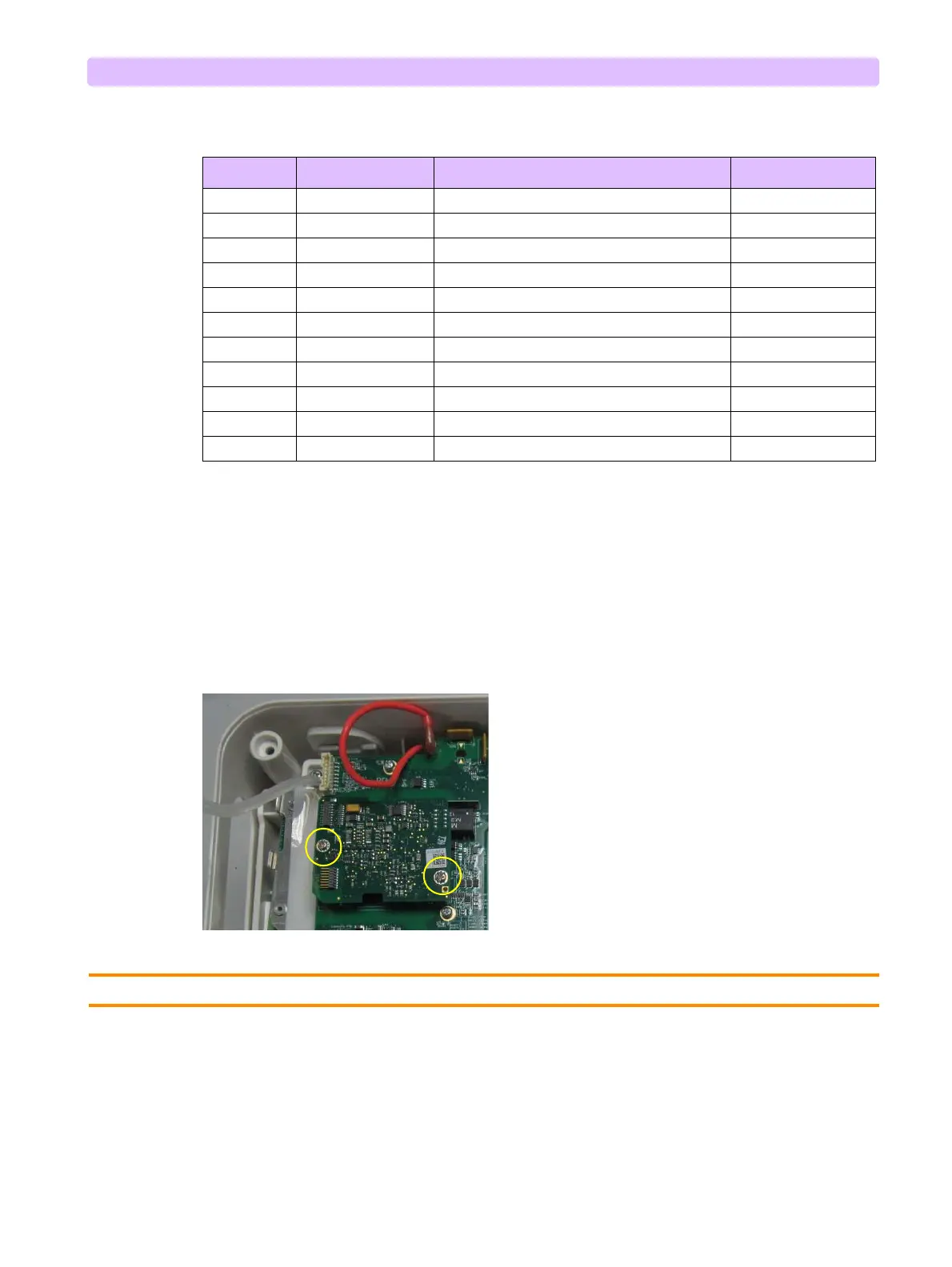
1 Remove the two M 3x6 screws on SpO
2
PCA, see Figure 94.
Figure 94 SpO2 PCA
2 Unplug the SpO
2
PCA from the Processor PCA.
CAUTION: Be careful not to bend or damage the pins when you removing the SpO2 cable and PCA.
Replacement
1 Plug in the SpO
2
PCA on the Processor PCA until fully seated.
2 Install the two M 3x10 screws.
3 Install the Measurement Module. See “Measurement Module” on page 107.
4 Close the Case. See “Closing the Case” on page 149.
Table 30 Therapy PCA Cable Connection Sockets
PCA Mark Description Connects To Disconnect By
J1 2-wire buddle AC Power Assembly Loosen latch, pull
J2 4-wire buddle Battery PCA Loosen latch, pull
J5 4-pin buddle Battery PCA Gently unplug
J9 spade connector Therapy Capacitor Cable (red) Pull, wiggle
J11 spade connector Therapy Capacitor Cable (white) Pull, wiggle
J8 spade connector Therapy PCA High Voltage Cable (red) Pull, wiggle
J10 spade connector Therapy PCA High Voltage Cable (white) Pull, wiggle
J12 3-pin buddle Fan1 (close to AC Power Module) Gently unplug
J13 3-pin buddle Fan2 (close to Internal Resistors) Gently unplug
J18 spade connector Internal Resistors Module Pull, wiggle
J19 spade connector Internal Resistors Module Pull, wiggle