5: Performance Verification Performance Verification Procedures
170
The steps used for these tests and the acceptable ranges of values are derived from local and international
standards but may not be equivalent. These tests are not a substitute for local safety testing where it is
required for an installation or a service event.
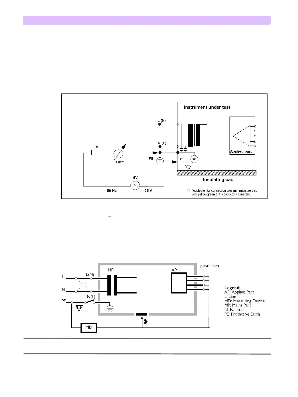
Protective Earth Resistance
Figure 132 illustrates the protective earth resistance measurement of Efficia DFM100.
Figure 132 Efficia DFM100 Protective Earth Resistance Test Diagram
Acceptable test results:
Maximum impedance x <
100m(IEC 60601-1 and UL 60601-1). Records as “aaa”.
Leakage Currents
Figure 133 illustrates the Efficia DFM100 circuitry.
Figure 133 Efficia DFM100 Leakage Current Test Diagram
NOTE: ˙ Check accessible conductive parts for touch current (enclosure leakage current), but not for protective
earth resistance because they are not protectively earthed.