LIFEPAK 15 Monitor/Defibrillator
Service Manual
Replacement Procedures
System (A01)/Therapy (A04) PCB Assembly Replacement
Section Menu Section Contents Procedures Back Index
235
8
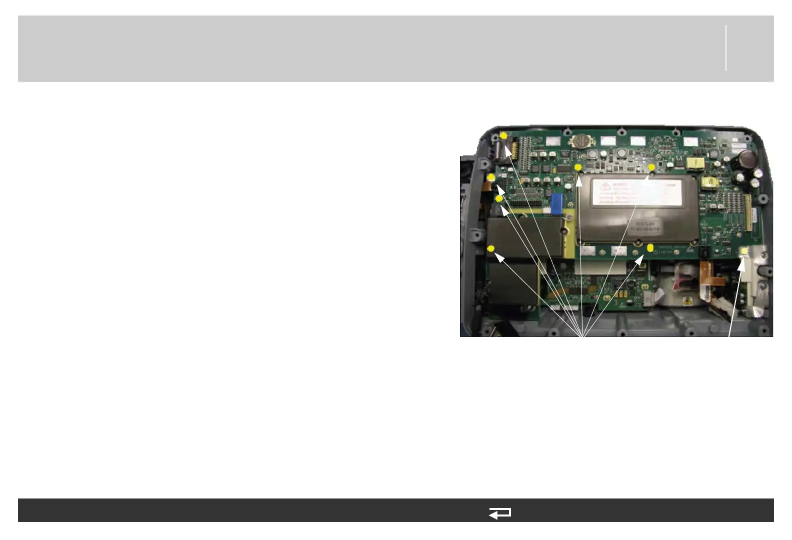
3. Remove the seven screws (202253-761) and one screw with
washer (3207337-312) that secure the system PCB to the rear
case. Discard the screws.
NOTE: The screw that is in the ECG shield can easily be
missed as part of screw removal. Ensure that all
screws are removed prior to lifting the system/
therapy PCB assembly.
4. Set the rear case upright and move the system/therapy PCB
assembly towards the front of the case to gain access to the rear
therapy PCB connectors.
Figure 8.37—System/therapy PCB screw locations
To remove the system/therapy PCBs as a single unit from the rear case: (Continued) 9 steps, (Page 3 of 6)
system/therapy mounting screws
(7 places)
mounting screw with washer
(1 place)