LIFEPAK 15 Monitor/Defibrillator
Service Manual
Replacement Procedures
Power PCB (A03) Replacement
Section Menu Section Contents Procedures Back Index
259
8
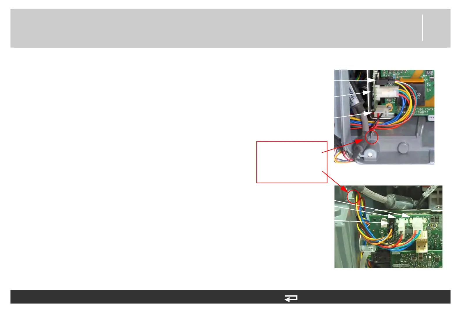
5. For V1 Power PCB (3206749-003): Connect
battery pins/power PCB cable (W10) to the power
PCB at J11 and J13.
6. For V1 Power PCB (3206749-003): Route the
auxiliary power cable (W09) over the top of battery
pins/power PCB cable (W10). Connect auxiliary
power cable to the power PCB at J15.
7. For V2 Power PCB (3302519-002): Connect
battery pins/power PCB cable (W10) to the power
board at J11.
8. For V2 Power PCB (3302519-002): Connect the
auxiliary cable (W09) 2-pin cable to the power PCB
at J15-A. Route the auxiliary power (W09) 4-pin
cable over the top of battery pins/power PCB cable
(W10) and connect to the power PCB at J15-B.
9. Route system connector wires so that they have
clearance behind the power PCB.
To install the power PCB (A03) into the rear case: (Continued) 14 steps, (Page 3 of 4)
Figure 8.57—Power PCB connections
V2
V1
PINCH HAZARD:
Route W09 cable over
W10 cable and connect
to J15. Routing will
keep wires below rear
case tab
J13 connection
(W10)
J11 connection
(W10)
J15 connection
(W09)
J15-A connection
(W09)
J11 connection
(W10)
J15-B connection
(W09)