LIFEPAK 15 Monitor/Defibrillator
Service Manual
Replacement Procedures
Power PCB (A03) Replacement
Section Menu Section Contents Procedures Back Index
258
8
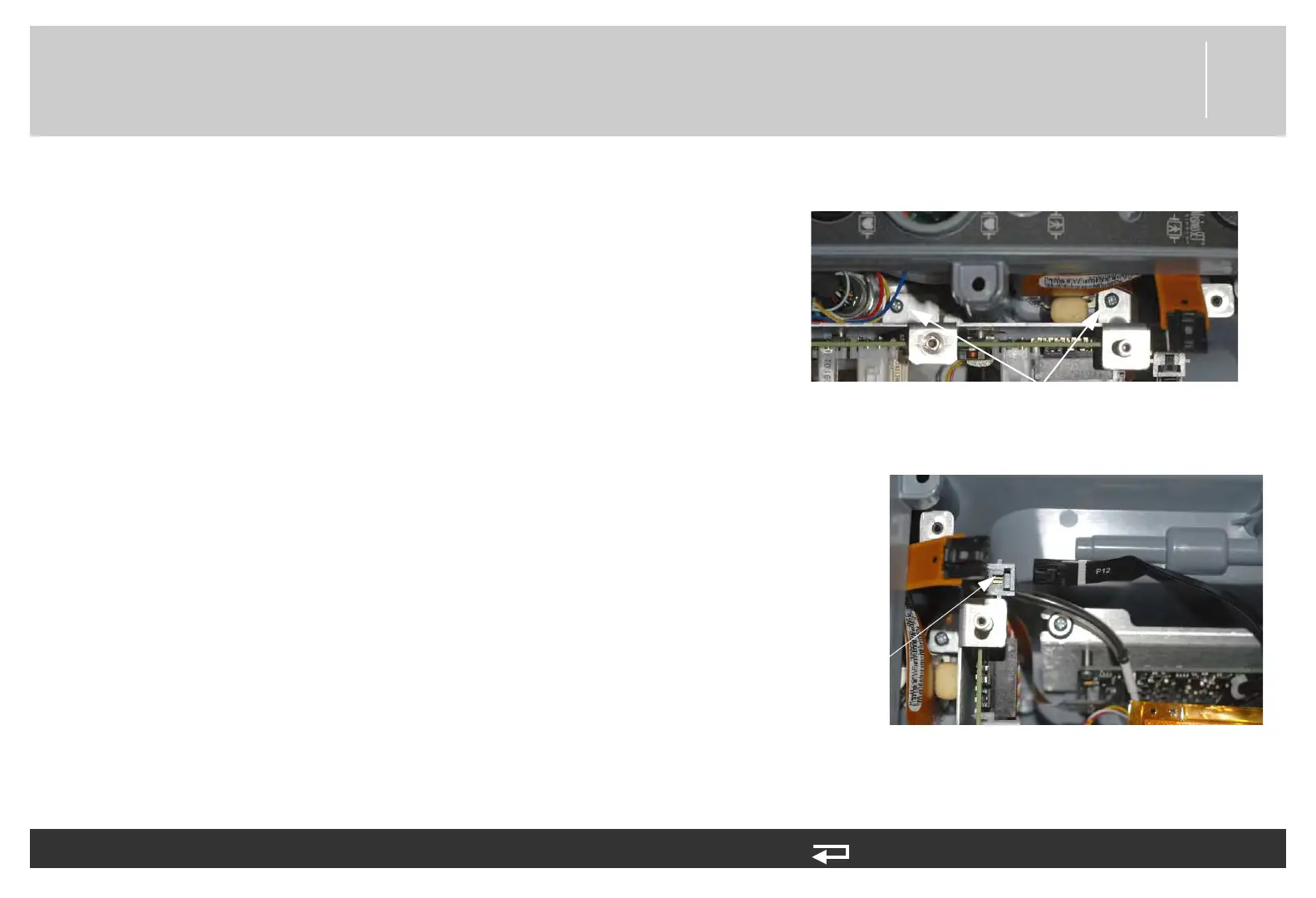
3. Mount the power PCB in the case and secure the
bracket (3206961-001) to the rear case using two
new screws (202253-761); torque to 6.8 in-lb.
NOTE: Ensure that the W28 - FRS
assembly CO2 tubing/ wiring is
above the SpO2 cable and not
kinked as it comes through the
space provided along right side of
the power PCB.
4. Connect power/contact PCB cable (W05) to the
power PCB at J12.
To install the power PCB (A03) into the rear case: (Continued) 14 steps, (Page 2 of 4)
mounting screws
(2 places)
Figure 8.55—Power PCB screw
locations
J12
connection
Figure 8.56—Power PCB J12 connection