LIFEPAK 15 Monitor/Defibrillator
Service Manual
Replacement Procedures
Power PCB (A03) Replacement
Section Menu Section Contents Procedures Back Index
257
8
Installing the Power PCB (A03)
Some parts mentioned in this procedure are optional and may not apply to your device.
To install the power PCB (A03) into the rear case: 14 steps, (Page 1 of 4)
NOTE: When installing a new power PCB, use either
the Power PCBA Repair Kit, V1 (MIN
3305431-006) (p. 500) or Power PCBA
Repair Kit, V2 (MIN 3305431-030) (p.
518).
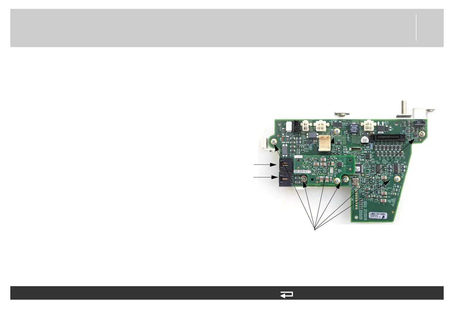
1. Secure the power PCB to the mounting bracket
(3206961-001) using the six new screws
(202253-761); torque to 6.8 in-lb.
2. Connect the W08 - system connector cables to J09
and J10. If there is an NIBP option, ensure that the
NIBP tube is routed above the system connectors.
Figure 8.54—Power PCB mounting bracket screw locations
screws mounting PCB to bracket
(6 places)
J9
connection
J10
connection