LIFEPAK 15 Monitor/Defibrillator
Service Manual
Replacement Procedures
SpO2 PCB (A16) Replacement
Section Menu Section Contents Procedures Back Index
283
8
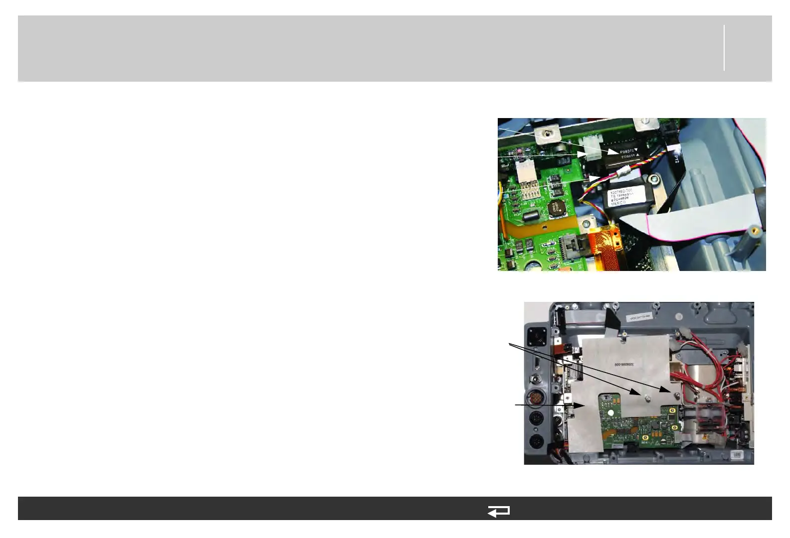
8. Route CO2 adapter cable (W30) above the power/system cable
as shown.
9. Install power/system cable (W01) to the power board at J17.
10. Install the OEM shield (3208298-000). Route below the J8
connector and the J11 and J15 connectors.
11. Install the power/therapy cable (W02) (3009726-05) to J8 on
the power PCB.
12. Install the system/therapy PCB assembly as described in
System (A01)/Therapy (A04) PCB Assembly Replacement (p.
232).
13. Reassemble the case as described in Reassembling the Case (p.
184).
To install the SpO2 Module in the rear case (see Figure 9.21 on p. 413): (Continued) 13 steps, (Page 4 of 4)
Figure 8.76—Power/system PCB connections
J17
connection
J8
connection
CO2
adapter
cable
standoff
locations
Figure 8.77—OEM shield
OEM shield