LIFEPAK 15 Monitor/Defibrillator
Service Manual
Replacement Procedures
SpO2 PCB (A16) Replacement
Section Menu Section Contents Procedures Back Index
282
8
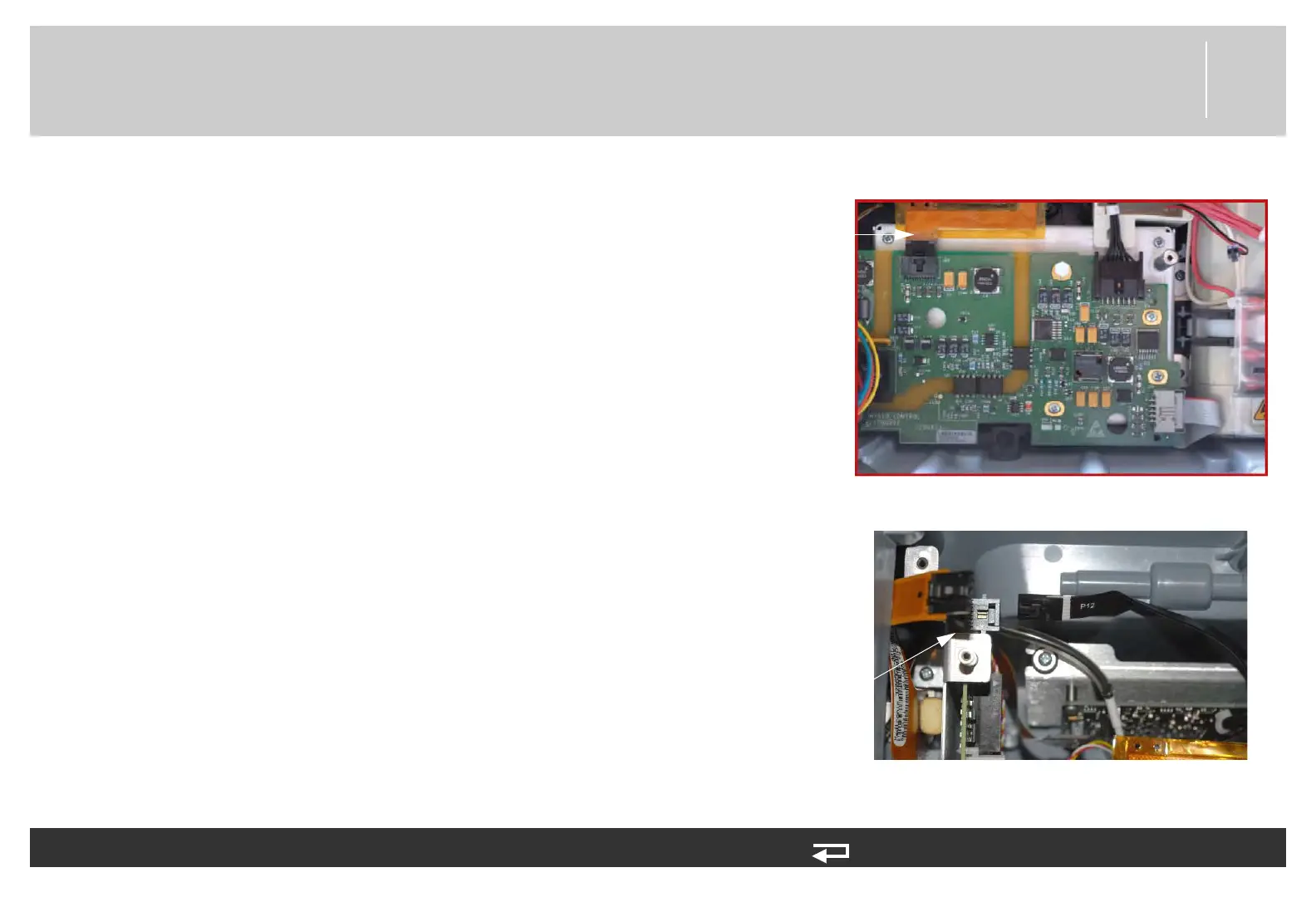
6. Connect the SpO2/OEM cable (W21) (3207000-004) to the
OEM PCB at J26.
7. Connect the power/contact cable (W05) to the power board at
J12.
To install the SpO2 Module in the rear case (see Figure 9.21 on p. 413): (Continued) 13 steps, (Page 3 of 4)
J26
connection
Figure 8.74—SpO2 connection to OEM PCB
J12
connection
Figure 8.75—Power PCB J12 connection