Function Description
Operating Manual PMCprotego D.48, PMCprotego D.72
1001735-EN-04
76
Setting the parameters:
The following can be set in the “Encoder Emulation” window in the commissioning software:
} Position of the zero pulse within one mechanical revolution (NI-OFFSET parameter)
} Resolution (before multiplication) in counts/revolution
} ENCMODE = 1: Incremental encoder compatible signals from the resolver or SinCos
encoder
} ENCMODE = 3: Encoder signal from X1 is available at X5
Parameter
ENCMODE Encoder type Resolution Zero pulse
1= incremental en-
coder
Resolver 256 … 4096 (2
8
...
2
12
)
One per revolution
(only when
A=B=1)
SinCos encoder 256 … 524288 (2
8
…
2
19
)
One per revolution
(only when
A=B=1)
3 = Incremental en-
coder interpolation
SinCos encoder 4 ... 256 (2
2
... 2
7
)
TTL counts * resolu-
tion of encoder
Encoder signal
passed from X1 to
X5
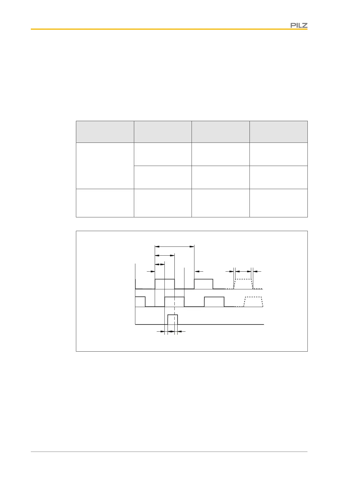
Timing diagram for the incremental encoder signal:
A
B
NI
5 V
5 V
5 V
aa a a
tvtv
tdtd
90°
180°
360°
} a: Edge spacing ≥ 0.2 μs
} tv: Edge steepness ≤ 0.1 μs
} NI – td: Delay ≤ 0.1 μs
} |ΔU| ≥ 2 V/20 mA
} Default count direction: Upwards, facing the motor axis when rotating clockwise
Output of SSI signals
Functions:
With this encoder emulation, positional data for the SSI interface is prepared from the exist-
ing output signals from the resolver or SinCos encoder.
 Loading...