Function Description
Operating Manual PMCprotego D.48, PMCprotego D.72
1001735-EN-04
77
} A max. 32Bits are transferred.
} Singleturn: The leading 12 to 16Bits are zero, the following 16Bits indicate the posi-
tion. On 2-pole resolvers the position value refers to a full revolution of the motor; on 4-
pole resolvers it refers to half a revolution and on 6-pole resolvers to one third of a re-
volution.
} Multiturn: The leading 12 to 16Bits indicate the number of revolutions; the following 16
bits state the position.
Revolution
SSIREVOL
Bit
15 14 13 12 11 10 9 8 7 6 5 4 3 2 1 0
14 13 12 11 10 9 8 7 6 5 4 3 2 1 0
13 12 11 10 9 8 7 6 5 4 3 2 1 0
12 11 10 9 8 7 6 5 4 3 2 1 0
11 10 9 8 7 6 5 4 3 2 1 0
Position
Bit 15 14 13 12 11 10 9 8 7 6 5 4 3 2 1 0
Setting the parameters:
The following can be set in the “Encoder Emulation” window in the commissioning software:
} Clock frequency of the SSI evaluation (1.3 μs or 10 μs)
} Signal sequence in grey format (standard) or binary format
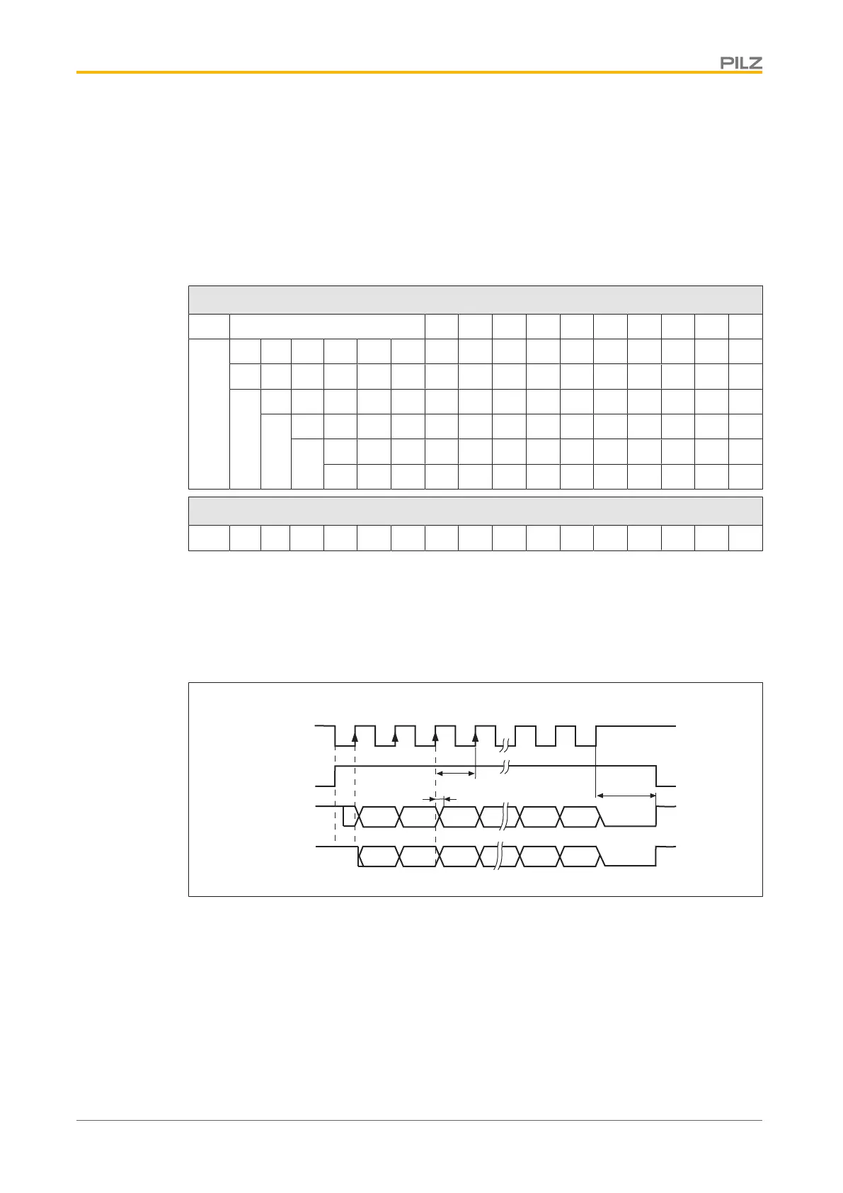
Timing diagram:
Clock
Monoflop
Gray
Binär
1 2 3
4
2
31
2
0
G31
G0
T
t
v
33
32
t
p
Fig.: Timing diagram in gray and binary code
} Switch over time for data t
v
≤ 300 ns
} Min. period length T = 600 ns
} Timeout t
p
= 1.3 μs or 10 μs (SSITOUT parameter)
} Output |ΔU|
} I ≥ 2 V/20 mA
} Input |ΔU| ≥ 0.3 V
} Default count direction: Upwards, facing the motor axis when rotating clockwise
 Loading...