User’s Manual of WGSW-28040 / 28040P
25
Off: If LNK/ACT LED light-> indicate that the port is operating at 100Mbps
If LNK/ACT LED Off -> indicate that the port is link down
■ Alert
LED Color Function
PoE PWR Green Lights to indicate that the power supply failure
FAN1 Green Lights to indicate that the FAN1 failure
FAN2 Green Lights to indicate that the FAN2 failure
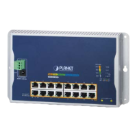
2.1.3 Switch Rear Panel
The rear panel of the Managed Switch indicates an AC inlet power socket, which accepts input power from 100 to 240V AC,
50-60Hz. Figure 2-5 & Figure 2-6 shows the rear panel of these Managed Switches
WGSW-28040 Rear Panel
Figure 2-5 Rear panel of WGSW-28040
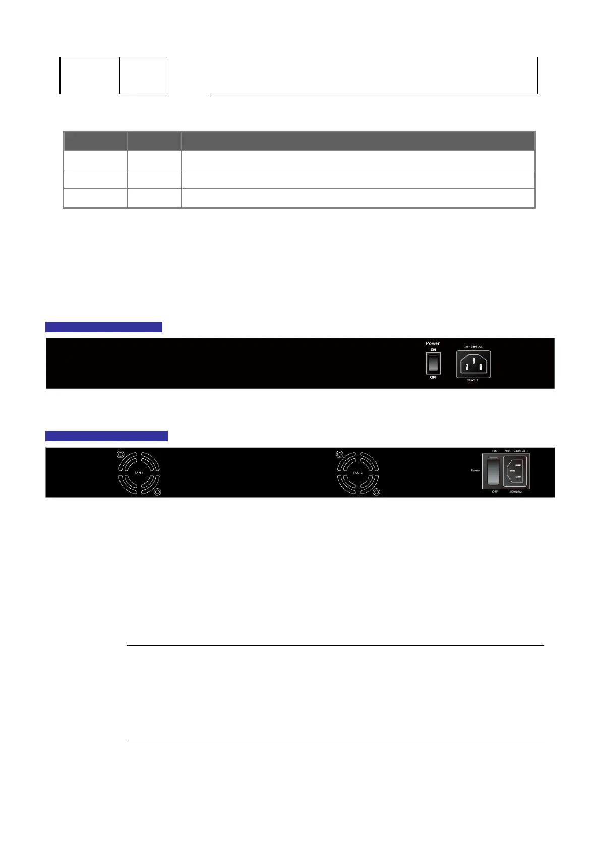
WGSW-28040P Rear Panel
Figure 2-6 Rear panel of WGSW-28040P
■ AC Power Receptacle
For compatibility with electric service in most areas of the world, the Managed Switch’s power supply automatically adjusts
to line power in the range 100-240V AC and 50/60 Hz.
Plug the female end of the power cord firmly into the receptalbe on the rear panel of the Managed Switch. Plug the other
end of the power cord into an electric service outlet then the power will be ready.
Power Notice:
The device is a power-required device, it means, it will not work till it is powered. If your networks should
active all the time, please consider using UPS (Uninterrupted Power Supply) for your device. It will
prevent you from network data loss or network downtime.
In some area, installing a surge suppression device may also help to protect your Managed Switch from
being damaged by unregulated surge or current to the Switch or the power adapter.

 Loading...