Chapter 1-First Time Installation and Configuration
Polycom, Inc. 1-39
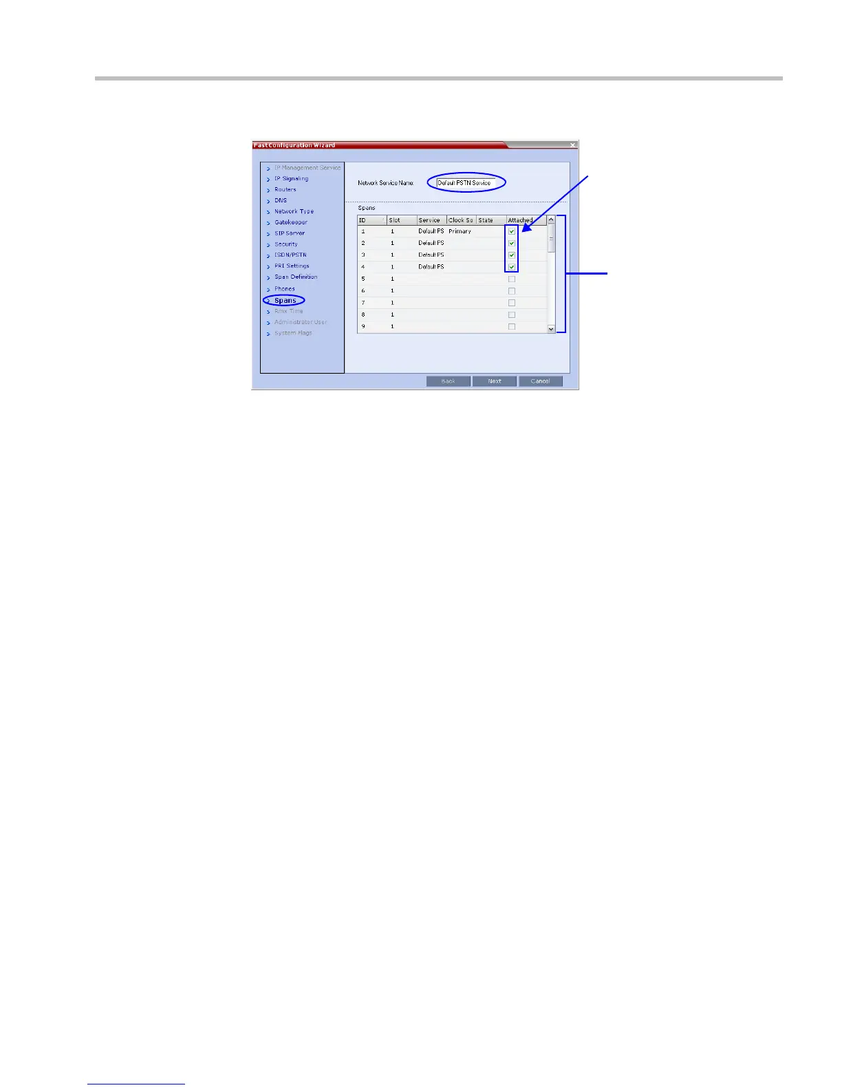
The Spans dialog box opens displaying the following read-only fields:
— ID – the connector on the ISDN RTM card (PRI1 to PRI12).
— Slot – the MPM+ card that the ISDN RTM card is connected to
(MPM 1 or MPM 2).
— Service – the ISDN/PSTN Network Service to which the span is assigned.
— Clock Source – indicates if ISDN signaling synchronization is being supplied by the
Primary or Secondary clock source. The first span to synchronize becomes the
Primary clock source.
— State – the System Alert level of the span (Major, Minor). If there are no span related
alerts, this column contains no entries.
25 Click the check boxes in the Attached field to attach spans (E1 or T1 PRI lines) to the
network service named in the Network Service Name field.
The Spans Table displays the configuration of all spans and all ISDN network services in
the system.
When using the Fast Configuration Wizard during First Entry Configuration, you are
defining the first ISDN/PSTN Network Service in the system. Spans can only be attached
to this service.
Additional ISDN/PSTN Network Services can be defined by using the ISDN/PSTN
Network Services > New PSTN Service button in the RMX Web Client.
Spans can be attached to, or moved between ISDN network services by using the ISDN/
PSTN Network Services > ISDN Properties > Spans tab in the RMX Web Client
.
Each ISDN RTM card can support either 7 E1 or 9 T1 PRI lines (E1 and T1 connections
cannot be used simultaneously).
26 Click Next.