3-462--11052
b. Lubricate the end of the crankshaft with clean oil.
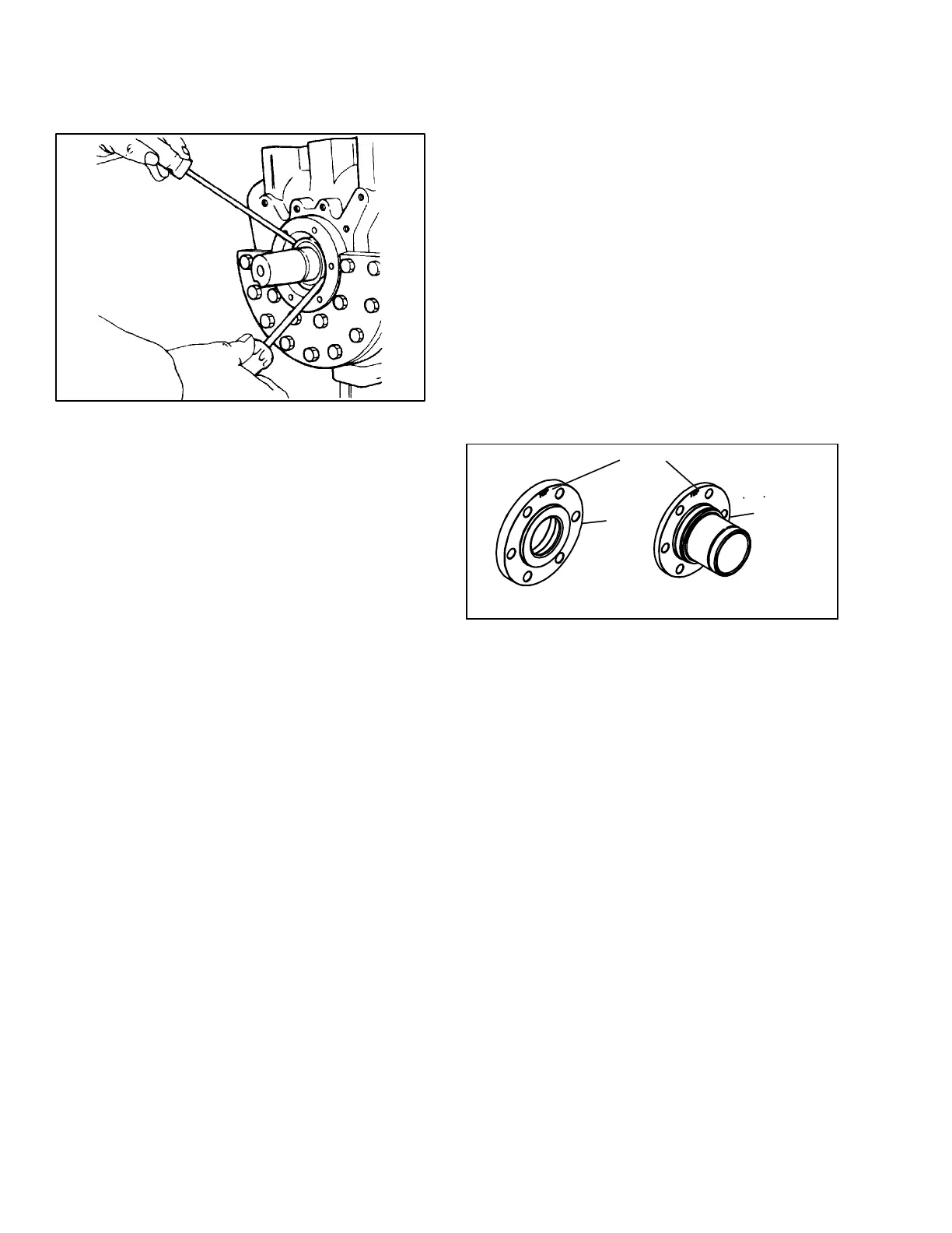
c. Using two long screwdrivers, pry out the shaft seal but
do not damage the gasket surface or the crankshaft.
(See Figure 3-8)
Figure 3-8. Shaft Seal Removal
3.6.2 Reassembly
NOTE
Install a new shaft seal assembly and cover
gasket, with the shaft seal cover/clutch
mounting hub. Never install a used seal
assembly or gasket. A new rotor should never
be installed with a used stator. When installing
the seal assembly, use care not to damage the
rotor or stator.
a. Remove the NEW rotor from new seal assembly.
Lubricate shaft and the neoprene seal bellows where
it contacts the shaft with clean/fresh compressor oil.
Slide the seal assembly onto shaft until the neoprene
bellows starts to grip the shaft.
b. Install the OLD rotor in the new seal seat. Install two
capscrews in opposite sides of the old cover/mount-
ing hub. Draw up capscrews evenly to properly posi-
tion new seal assembly against the shoulder on the
crankshaft. Remove the capscrews and old rotor and
cover plate/mounting hub.
c. Install the NEW rotor. Ensure that notches in rotor are
aligned with two small knurls inside the seal seat.
Install the new cover plate and gasket.
d. Remove the old stator and O--ring from the shaft seal
cover/clutch mounting hub.
e. Inspect the lip seal that is still in the cover/clutch
mounting hub. If it shows any signs of damage or
wear remove it.
f. Install the lip seal into the cover/clutch mounting hub.
Insure that the back side of the lipseal seats on the
shoulder machined in the cover/clutch mounting hub.
g. Using clean refrigerant oil, lubricate the new O--ring
and install it into the outside groove of the new stator
being careful not to touch the sealing surfaces of the
stator with your fingers.
NOTE
Do not touch the sealing surfaces with your
fingers. If the sealing surfaces become
contaminated, clean with isopropyl alcohol and
a clean dry lint--free cloth.
h. Install the stator into the cover/clutch mounting hub.
Insure that the back side of the stator seats to the lip
seal.
NOTE
The shaft seal cover or clutch mounting hub on
this compressor must be oriented so that the oil
communication hole in the cover/hub lines up
correctly with the port in the crankcase. The
cover/hub should mount flush with the
crankcase with the “TOP” stamp on the pump
oriented straight up.
i. Assemble the seal cover/clutch mounting hub, the
gasket and the six hex head screws on to the com-
pressor, paying attention to the orientation of the cov-
er/hub (see Figure 3-9).
1 Seal Cover
2 Mounting Hub
1
2
“TOP”
Figure 3-9. TOP Orientation
j. Align the gasket and install the six capscrews in the
mounting flange. Refer to Table 3-1, for applicable
torque values.
3.7 COMPRESSOR RUNNING GEAR REMOVAL
In order to disassemble Piston, Rod and Rings, first the
cylinder heads and valve plate aseemblies, oil pump
and bearing head assemblies and shaft seal must be
removed. (Refer to sections 3.4, 3.5 and 3.6 ).
3.7.1 Bottom Plate, Strainer, and Connecting Rod
Caps
a. Turn the compressor over, bottom side up, and re-
move the bottom plate. (See Figure 3-10) Scrape off
gasket.
b. Remove the oil strainer.