Section 06: ELECTRICAL
PA1562
39
CAUTION
Use a soft cloth to clean the parking and front
turn signal lamp.
9.1.3 Headlight Adjustment
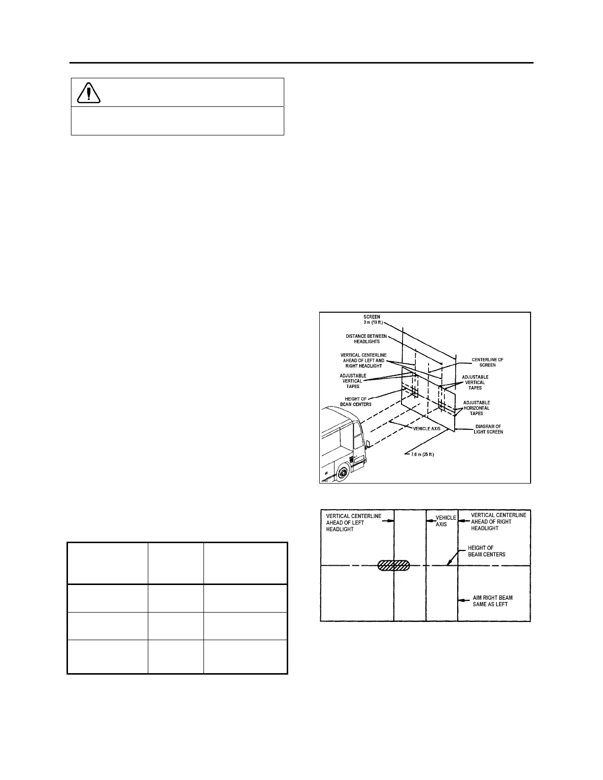
1. Headlight aiming and inspection can be
accomplished by visual means. This is done
on a screen located at a distance of 25 feet
(7,6 m) of the headlights. It should be of
adequate size with a matte-white surface
well shaded from extraneous light and
properly adjusted to the floor area on which
the vehicle stands. Provisions should be
made for moving the screen or its vertical
centerline so that it can be aligned with the
vehicle axis. In addition to the vertical
centerline, the screen should be provided
with four laterally adjustable vertical tapes
and two vertically adjustable horizontal
tapes.
2. The four movable vertical tapes should be
located on the screen at the left and right
limits called for in the specification with
reference to centerlines ahead of each
headlight assembly.
3. The headlight centerlines shall be spaced
either side of the fixed centerline on the
screen by ½ the lateral distance between
the light source centers of the pertinent
headlights. The horizontal tapes should be
located on the screen at the upper and
lower limits called for in the specification
with reference to the height of beam centers
and the plane on which the vehicle rests, not
the floor on which the screen rests (Fig. 26).
TABLE 1 – VERTICAL BEAM AIM GUIDELINES
Headlight
(centerline)
Mounting Height
Nominal
Vertical
Aim
Aim Inspection
Limits for Vertical
Aim
56 to 90 cm (22 to
36 inch)
0 Vertical 10 cm (4 inch) up to
10 cm ( 4 inch) down
90 to 120 cm (36 to
48 inch)
5 cm (2 inch)
down
5 cm (2 inch) up to 15
cm (6 inch) down
120 to 140 cm (48 to
54 inch)
6.4 cm (4
inch) down
4 cm (1.5 inch) up to
16.5 cm (6.5 inch)
down
4. The nominal vertical aim position on lower
beam headlights shall be adjusted based on
the headlight mounting height, from the
ground to the light source center of the
headlight, according to table1.
5. High beam headlights are aimed so that the
center of the high-intensity zone is located
at the horizontal and straight ahead
vertically (Fig. 26).
6. Low beam headlights are aimed so that the
top edge (the cutoff) of the high-intensity
zone is at the vertical location as per Table
1 and the left edge of the high-intensity zone
is at the vertical centerline of the headlight
(Fig. 27).
7. The inspection limits for high-beam
headlights shall be with the center of the
high-intensity zone from 10 cm (4 in) up to
10 cm (4 in) down; and, from 10 cm (4 in)
left to 10 cm (4 in) right on a screen at 7.6 m
(25 ft) (Fig. 28).
FIGURE 26: ALIGNMENT OF HEADLIGHT AIMING
SCREEN
06502
FIGURE 27: HIGH-INTENSITY ZONE (SHADED AREA) OF
A PROPERLY AIMED UPPER BEAM ON THE AIMING
SCREEN 7.6 M (25FT) IN FRONT OF VEHICLE
06503