Repair and Testing Instructions for T1 Page 19
Alternator 0120 689 552 Edition 001
All rights rest with Robert Bosch Corp, including patent rights. All rights of use of reproduction and publication rest with R. B. Corp.
UA/ASV 04.12.98 T1ALTFinal.DOC
b. Using a Diode Tester
i) Connect the negative (black) lead of the tester to the collector end shield and the positive (red) lead
to each of the stator connection solder joints. No current should pass through the rectifier assembly.
ii) Connect the positive (red) lead of the tester to the collector end shield and the negative (black) lead
to each of the stator connection solder joints. Current should pass through the rectifier assembly.
iii) Connect the positive (red) lead of the tester to the B+ Terminal and the negative (black) lead to
each of the stator connection solder joints. No current should pass through the rectifier assembly.
iv) Connect the negative (black) lead of the tester to the B+ Terminal and the positive (red) lead to
each of the stator connection solder joints. Current should pass through the rectifier assembly.
v) Connect the positive (red) lead of the tester to the D+ Terminal and the negative (black) lead to
each of the stator connection solder joints. No current should pass through the rectifier assembly.
vi) Connect the negative (black) lead of the tester to the D+ Terminal and the positive (red) lead to
each of the stator connection solder joints. Current should pass through the rectifier assembly.
If the rectifier assembly fails any test, one or more of the diodes are defective and the whole assembly must be
replaced.
9.7 Removal and Testing of Stator Assembly
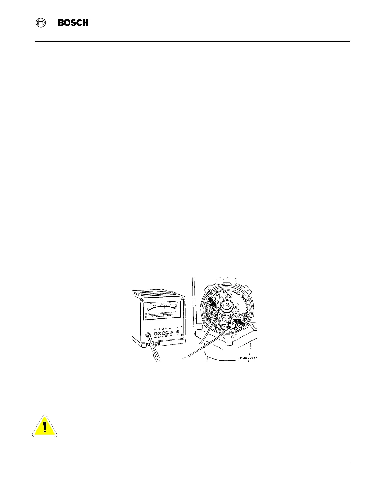
1. With tester WPG 012.00 or Multimeter MMD 302 set to read 0 to 0.5 W, test the resistance of the stator
while it is still attached to the rectifier assembly. Connect the test leads between the phase outputs of the
stator. Repeat the test until all three phases of the stator has been tested. A good stator will read between
0.036 W and 0.040 W. (Figure 12)
2. Unsolder the stator phase connections from the rectifier assembly with a soldering gun or iron.
3. Bend open any bent-over lead connections with a screwdriver or pliers and pull the stator leads from the
rectifier eyelets.
Note: The insulation tester applies a voltage of 80 VAC to the stator. Voltages of 80V can be fatal.
When performing this test, observe care is used in handling the stator and any component or
surface that is exposed to the stator. Use insulated gloves and do not touch the work surface
until all tests are completed.
Figure 12 Stator Resistance Testing