Section 11: REAR AXLES
PA1562
7
1.12 AXLE SHAFT SEALING METHOD
The following method is to be used to ensure
that axle shaft installation is fluid-tight:
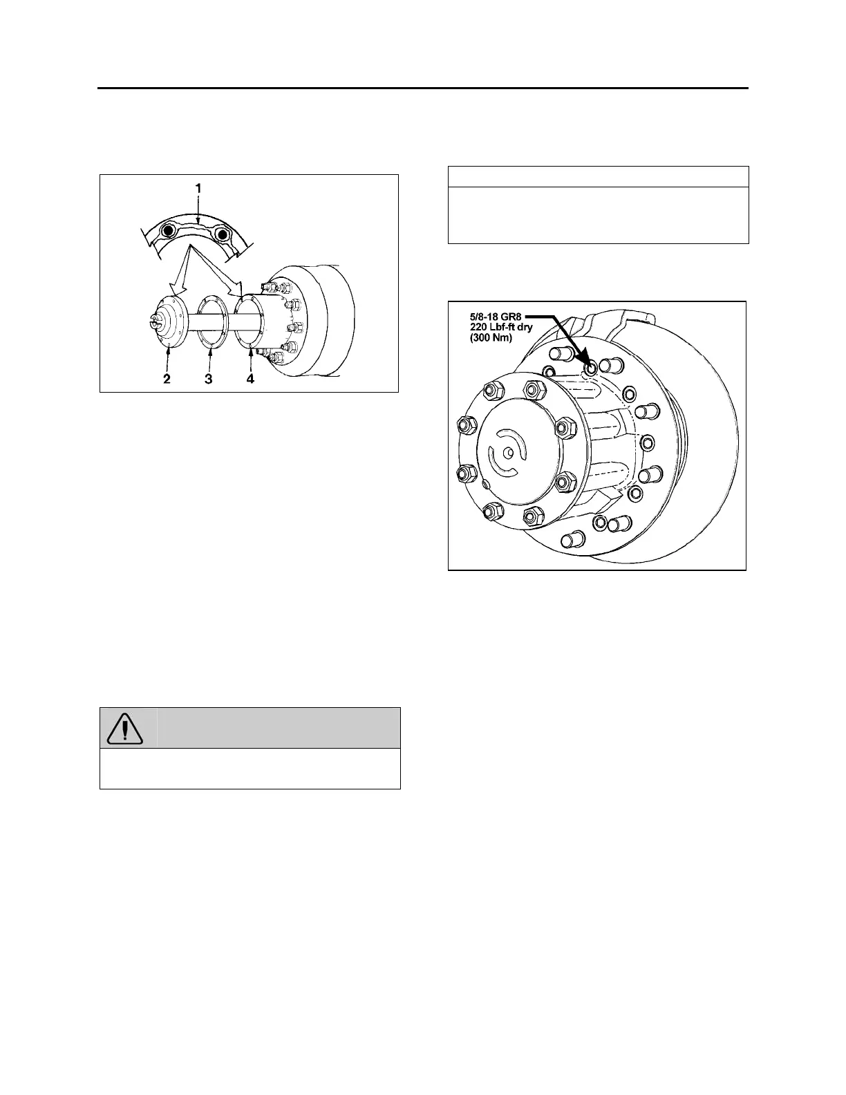
FIGURE 9: AXLE SHAFT INSTALLATION 11003
1 ................................................... Silicone sealant*
2 .............................................................. Axle shaft
3 ...................................................................Gasket
4 .............................................................Wheel hub
1. Clean the mounting surfaces of both the axle
shaft flange and wheel hub where silicone
sealant will be applied. Remove all old
silicone sealant, oil, grease, dirt and moisture.
Dry both surfaces.
2. Apply a continuous thin bead of silicone
sealant* (Prévost P/N 680053) on the
mounting surfaces and around the edge of all
fastener holes of both the axle shaft flange
and wheel hub.
*
GENERAL ELECTRIC Silicone Rubber Adhesive Sealant
RTV 103 Black.
WARNING
Carefully read cautions and instructions on the
tube of silicone sealant and its packing.
3. Assemble components immediately to permit
the silicone sealant to compress evenly
between parts.
a. Place a new gasket and then install the
axle shaft into the wheel hub and
differential carrier. The gasket and flange
of the axle shaft must fit flat against the
wheel hub.
b. Install the tapered dowels at each stud
and into the flange of the axle shaft. Use
a punch or drift and hammer if needed.
c. Install the lock washers and nuts on the
studs. Tighten nuts to the correct torque
value.
NOTE
Torque values are for fasteners that have a
light application of oil on the threads (refer to
Meritor Maintenance Manual).
9/16-18 plain nut: 110 - 165 lbf-ft (149 -224 Nm)
5/8-18 plain nut: 150 - 230 lbf-ft (203 - 312 Nm)
FIGURE 10: TORQUE SPECIFICATION
2. TAG AXLE
The tag axle is located behind the drive axle. It
carries a single wheel and tire on each side.
2.1 UNLOADING TAG AXLE
To reduce the turning radius, the air springs
pressure will be automatically reduced by 75%
when the coach is moving at speed lower than 5
mph (8 km/h) and with more than 1½ turn from
the steering.
2.2 RETRACTING TAG AXLE
The standard tag axle retraction system is
controlled by a valve located on the right lateral
console and enables unloading and raising the
tag axle (refer to the "OPERATOR'S MANUAL"
for location of controls). This system has been
designed for the following purposes:
1. Shortening of wheelbase, thus allowing tighter
turning in tight maneuvering areas such as
parking lots or when making a sharp turn.