Section 06: ELECTRICAL
PA1562
7
1.6 MULTIPLEX FUSES
The multiplex outputs are protected in current by
an internal “soft-fuse”. Each output has
programmed specific maximum amperage.
When an output is shorted, the current gets
above the limit and the soft-fuse intervenes to
turn the output OFF. The output stays OFF until
the "soft-fuse" is reset.
Turn the ignition key to the OFF position and
turn to the ON position again. This resets all
"soft-fuses".
There is also hardware fuses used to protect the
incoming power to the multiplex modules. These
fuses are located inside the VECF (Vehicle
Electrical Center Front) and VECR (Vehicle
Electrical Center Rear).
1.7 RELAYS
Relays are used to automatically energize or
deenergize a circuit from a remote location. The
relay draws a very low current to energize its
coil. Once the coil is energized, it develops a
magnetic field that pulls a switch arm closed or
open, to either energize or deenergize a given
component. As the control current required for
the coil is very low, the relay allows a remote
station to control a high energy circuit without
running great lengths of costly high capacity
cable, and also eliminates the need for high
amperage switches and heavy connectors.
NOTE
Each relay is identified with “12V” or “24V”
printed on its casing in order to identify the
coil operating voltage.
CAUTION
The Multiplex vehicle uses a VF4 relay
designed specially for Volvo that has different
internal characteristics than the current VF4
relay. It is important to use only the new part
marked Volvo as a replacement in Multiplex
vehicles. Regular relays have an inadequate
lifespan for Multiplex vehicles.
1.8 PRECAUTIONS
DANGER
Prior to working on a system inside vehicle,
make sure to cut electrical power and air
supply. A component could be supplied with
electricity even if the ignition switch is set to
the OFF position and/or a component could
be pressurized even if air tanks are emptied.
Always refer to the appropriate wiring and
pneumatic diagrams prior to working on
electrical and/or pneumatic systems.
NOTE
When the ignition switch is set to the OFF
position, the electrical components are not
energized except for the CECM (Chassis
Electronic Control Module), engine MCM,
transmission ECU, instrument cluster module,
the battery equalizer, the preheater system,
the wheelchair lift system and some Multiplex
modules which are energized during 15
minutes after the ignition has been set to the
OFF position. Prior to working on one of these
electrical components, set the master cut-out
switch in the rear electrical compartment to the
OFF position. If the vehicle will not be operated
for a long period (more than 2 weeks), it is
recommended, in order to prevent the batteries
from discharging, to trip main circuit breakers
(2, 4 and 6) located in the rear electrical
compartment to stop the small current drawn
by the radio preset station memory, the CECM
memory and the instrument cluster clock. Note
that the radio station presets will be erased,
same thing for the diagnostic codes history and
the instrument cluster clock will have to be
reset.
CAUTION
Prior to arc welding on the vehicle, refer to
"Multiplex Modules Disconnection Procedure
Prior To Welding" in section 00 GENERAL of
this manual to avoid serious damage to the
vehicle components.
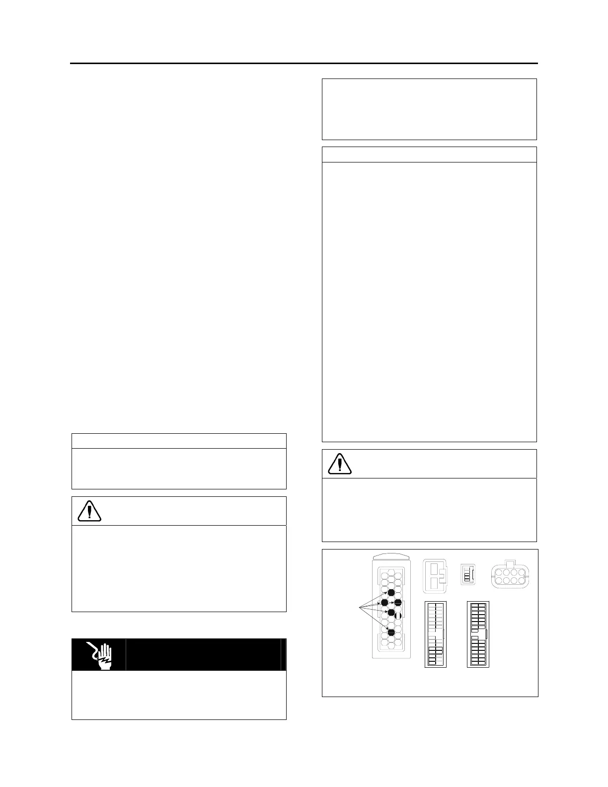
Black
Blue
Green
Green
Grey
Orange
Black
Red
Grey
Brown
Green
Yellow
1
2
1
5
14
30
1430
1
15
15
1
1
11
20
13
23
15
14
4
5
16
17
18
19
10
29
Guides, not
terminal
cavities
B
CD
E
FGH
24
BACK PROBING VIEW
FIGURE 3: MULTIPLEX MODULE CONNECTORS PIN-
OUT
06624