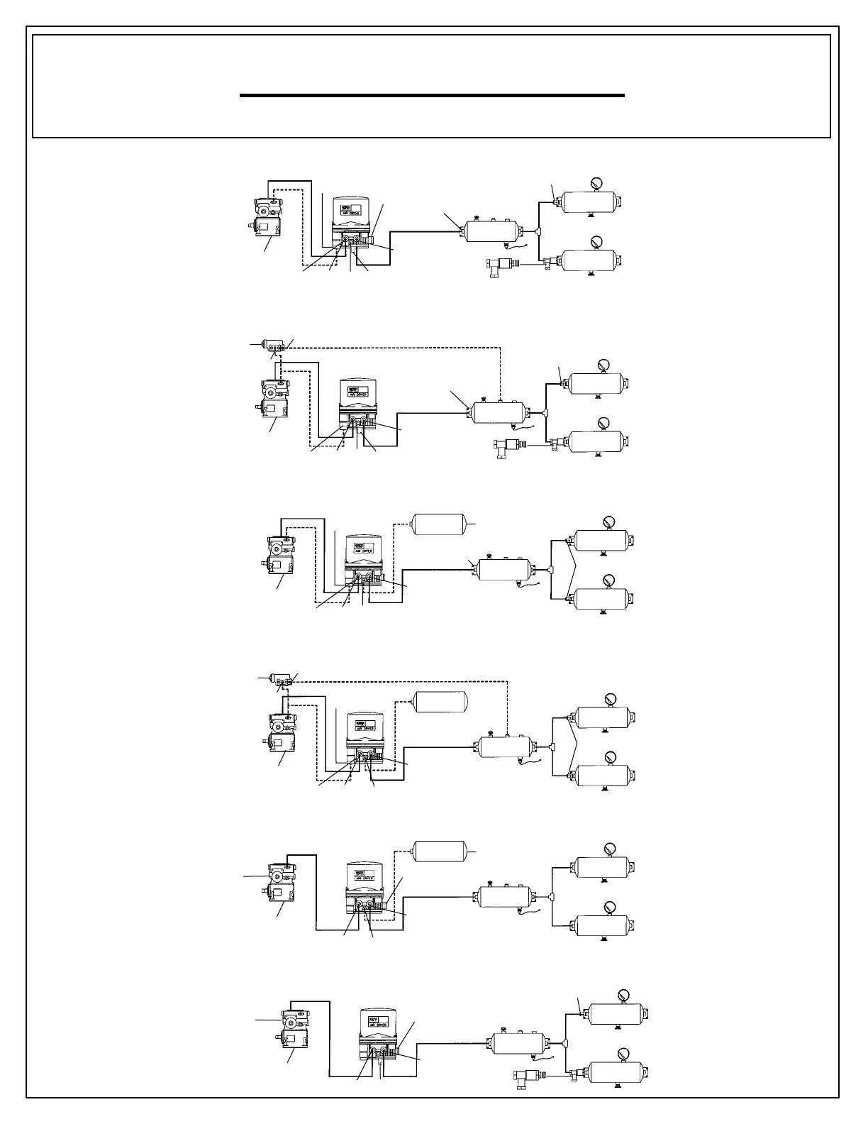
Application Schematics
FIG. 2.A. Standard System Regeneration with Integrated Governor
FIG. 2.B System Regeneration with External Governor
FIG. 2.C External Purge Tank Regeneration with Integrated Governor
FIG. 2.D External Purge Tank Regeneration with External Governor
FIG. 2.E. Blow Thru: External Purge Tank with Integrated Governor
FIG. 2.F. Blow Thru: System Regeneration with Integrated Governor
Compressor
Integrated
Governor
Dryer
Output
Port #21
Integrated Regeneration
Valve
Port #22
(plugged)
Dryer
Inlet
Port #1
Turbo-Protection
Valve
Pressure Controlled
Check Valve
No
Check Valve
Supply Tank
Primary
Secondary
Check Valve
Unloader
Port #4
Supply Tank
Primary
Secondary
Pressure Controlled
Check Valve
Check Valve
No
Check Valve
Dryer
Output
Port #21
Integrated Regeneration
Valve
Port #22
(plugged)
Dryer
Inlet
Port #1
Turbo-Protection
Valve
Compressor
Reservoir Port
Unloader
Port
Governor
Supply Tank
Primary
Secondary
Dryer
Output
Port #21
Port #22
Dryer
Inlet
Port #1
Turbo-Protection
Valve
Purge Tank
Can be mounted
Horizonally or Vertically
No
Check Valve
Check Valve
Unloader
Port #4
Compressor
Supply Tank
Primary
Secondary
Purge Tank
Can be mounted
Horizonally or Vertically
Check Valve
Dryer
Output
Port #21
Port #22
Dryer
Inlet
Port #1
Turbo-Protection
Valve
Compressor
Reservoir Port
Unloader
Port
Governor
Unloader
Port #4
Dryer
Output
Port #21
Port #22
Dryer
Inlet
Port #1
Integrated
Governor
Supply Tank
Primary
Secondary
Purge Tank
Can be mounted
Horizonally or Vertically
Compressor
Supply Tank
Primary
Secondary
Pressure Controlled
Check Valve
Check Valve
Dryer
Output
Port #21
Dryer Inlet
Port #1
Integrated Regeneration
Valve
Integrated
Governor
and
Governor
Adjustment
Compressor
Nat. Asp.
Inlet Only
Nat. Asp.
Inlet Only