Section 10: FRONT AXLE
PA1562
3
overhaul work is necessary, the axle assembly
should be removed.
CAUTION
Should removal of a locking device be required
when undergoing repairs, disassembly or
adjustments, always replace with a new one.
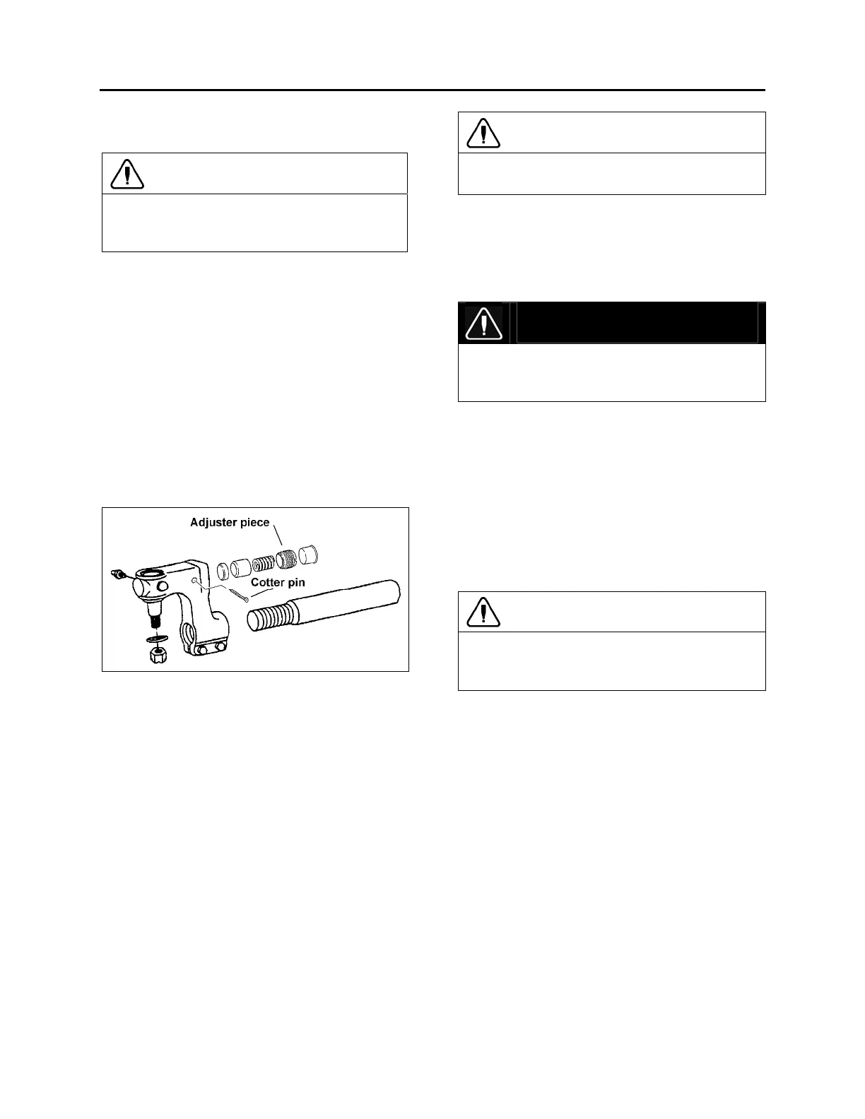
3.1 TIE ROD END PLAY ADJUSTMENT
If end play exceeds 0.047” (1.2 mm), readjust-
ment is necessary.
Remove protective cap, using a suitable tool ie:
a 1” x 1/8” x 9” long flat bar, tighten adjuster
piece fully home (SOLID) locating thrust cup
onto ball pin.
Still with tool located on adjuster piece, back off
carefully (LEAST AMOUNT) until adjuster piece
cotter pin is allowed to pass through body, then
remove tool.
Reinstall protective cap.
FIGURE 3: TIE ROD END PLAY ADJUSTMENT 10029
4. REMOVAL AND REPLACEMENT
The following procedure deals with the removal of
the front axle assembly. The method used to
support the axle assembly and suspension
components during removal and disassembly
depends upon local conditions and available
equipment.
4.1 REMOVAL
1. Raise the vehicle by its jacking points on the
body (see Section 18, ‘’Body’’ under heading
16; Vehicle Jacking Points) until vehicle body
is approximately 30 inches (760 mm) from the
floor. Place jack stands under frame. Remove
the wheels (if required, refer to Section 13,
‘’Wheels, Hubs and Tires’’).
CAUTION
Use only the recommended jacking points as
outlined in section 18 “Body”.
2. Exhaust compressed air from the air supply
system by opening the drain valve of each
reservoir.
3. Install jacks under axle jacking points to
support the axle weight.
DANGER
To help prevent injury caused by the axle rolling
off the jacks, these should be equipped with U-
adapters, or similar precautions must be taken
4. Disconnect the steering drag link from the
steering arm.
5. Remove the ABS sensors from their location
in hubs (if applicable).
6. Disconnect the height control valve link from
its support on the axle.
7. Disconnect air lines from front brake
chambers, and cover line ends and fittings to
prevent the entry of foreign matter.
CAUTION
Position the air lines and electric wires so they
will not be damaged while removing the front
axle assembly.
8. Proceed with steps a, b and c, while referring
to Section 16: ‘’Suspension’’.
a) Disconnect sway bar links from axle
brackets.
b) Remove shock absorbers.
c) Disconnect five radius rods: one
transversal and two longitudinal from
subframe, and two upper rods from axle.
9. Remove the bolts and nuts fixing the axle to
the left-hand and right-hand side air bellows
mounting supports.
10. Using the jacks, slowly lower the axle
assembly, and carefully pull away from
underneath vehicle.