Design and Operation
Return line pressure
2 Instructions on Design, Operation, Maintenance and Inspection
II. Design and operation
1
Design
The housing of the ZF Servocom steering gear houses the steering valve, the steering cylinder
and a complete manual steering gear.
The oil flow and the pressure required by the steering gear is supplied by an engine-driven pump.
To achieve this, the oil is taken in from the oil tank and fed back to the tank via the pump and
the steering gear.
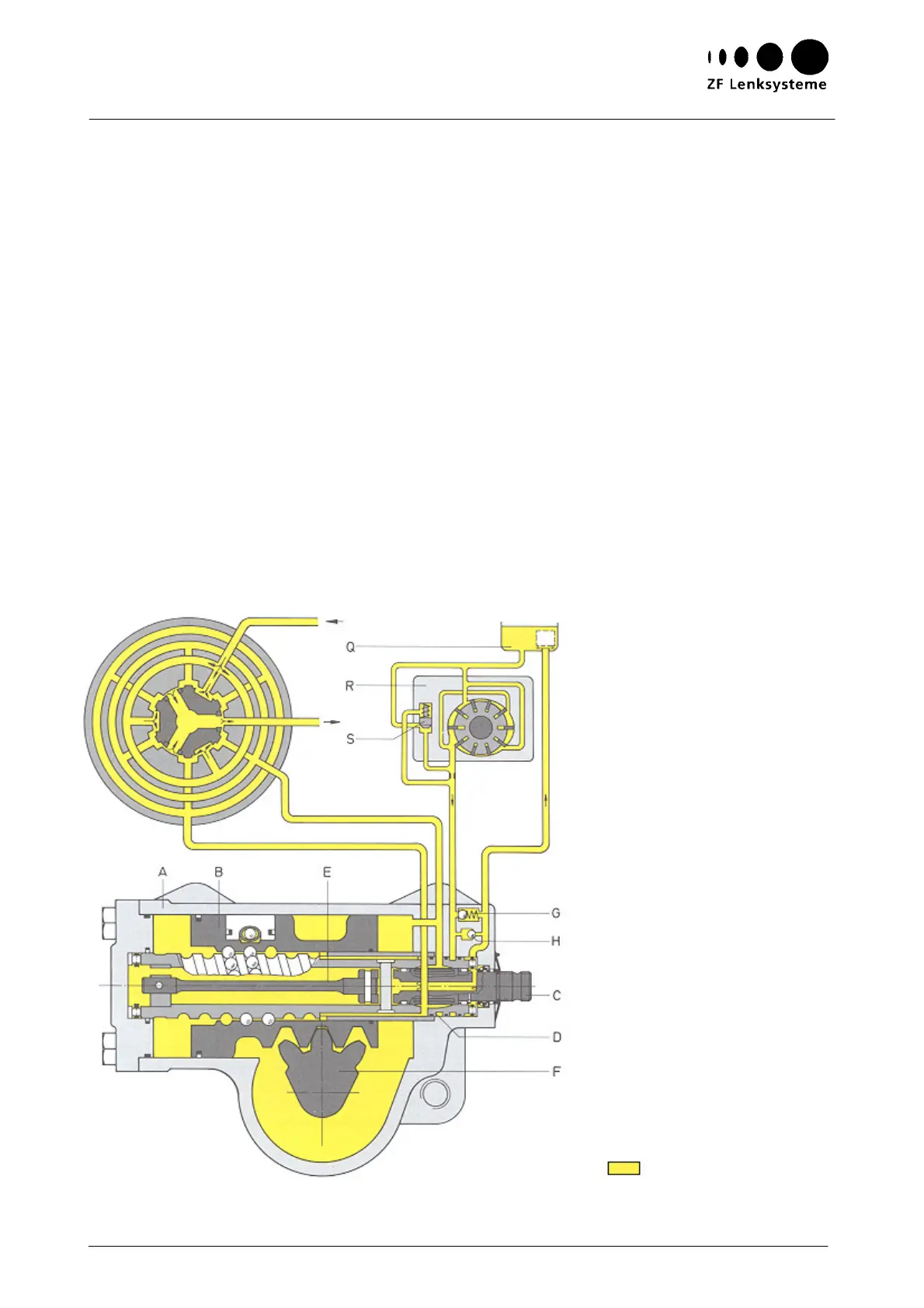
The housing (A) - see Fig. 1 - and the piston (B) have the function of a cylinder. The piston
transforms the rotation of the steering input shaft (C) and of the worm (D) into an axial motion
which it transmits to the sector shaft (F).
The piston (B) and the worm (C) are positively connected with each other by means of a ball chain.
As the worm rotates, the balls at one end of the chain are taken up by a recirculation tube and
fed back to the other end so that an endless ball chain is formed.
The teeth of the piston (B) and of the sector shaft (F) cause the sector shaft to rotate when the
piston is displaced.
Fig. 1
Valve rotor in
mid-position
A Housing
B Piston
C Valve rotor/steering
input shaft
D Valve sleeve/worm
E Torsion bar
F Sector shaft
G Pressure relief valve
H Replenishment valve
Q Oil tank
R Vane pump
S Flow limiting valve