Section 05: COOLING SYSTEM
PA1562
17
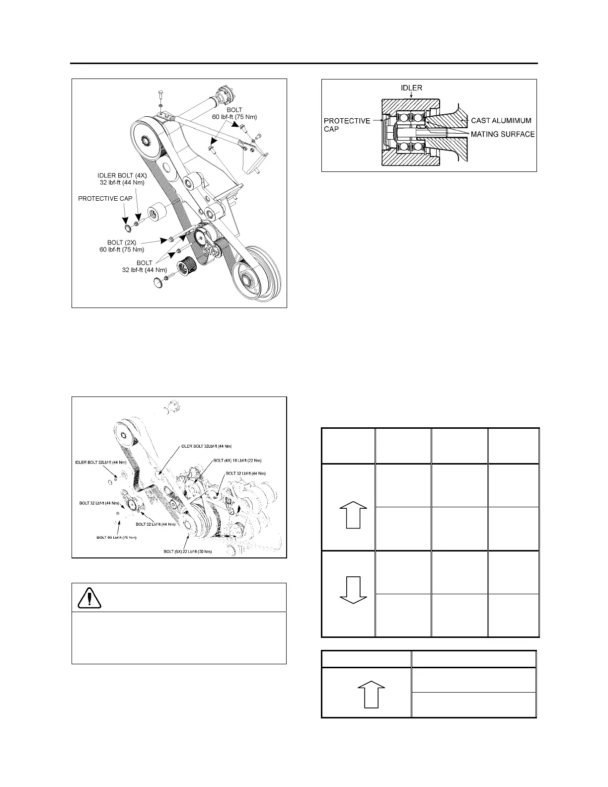
FIGURE 21: TIGHTENING SPECIFICATION (DDC S60
ENGINE)
05140
1. Remove the protective cap (replace with a
new one).
2. Unscrew the idler mounting bolt.
3. Replace idler with a new one.
FIGURE 22: TIGHTENING SPECIFICATION (VOLVO D13
ENGINE)
CAUTION
When installing the idler, make sure it rests
perfectly against the bearing surface on the
cast aluminum support. If not, the drive belt
may slip of the idler. See figure below.
FIGURE 23: IDLER MOUNTED ON THE CAST ALUMINUM
SUPPORT
4. Bolt the new idler on the cast aluminum
support. Tighten to 32 lbf-ft (44 Nm).
5. Place a new protective cap.
13. VARIABLE SPEED COOLING FAN
The cooling fan clutch has two thermostatically
controlled speeds, plus a neutral (clutch
disengaged). The engine control module
controls the speed by comparing data from
engine coolant temperature, charge air
temperature, Allison transmission oil
temperature and small A/C High side pressure
to a set of calibration data. The fan drive clutch
is electromagnetic; the engine control module
sends an electric current to regulate speed by
activating one magnetic coil for the first speed
and two magnetic coils for the second speed.
The settings are:
Engine
coolant
temp.
Air intake
temp.
Allison
trans. oil
temp.
208°F: fan
engages in
HIGH
SPEED
194°F: fan
engages in
HIGH
SPEED
230°F: fan
engages in
HIGH
SPEED
temperature
rising
203°F: fan
engages in
LOW
SPEED
176°F: fan
engages in
LOW
SPEED
216°F: fan
engages in
LOW
SPEED
203°F: fan
HIGH
SPEED
disengages
189°F: fan
HIGH
SPEED
disengages
225°F: fan
HIGH
SPEED
disengages
temperature
dropping
198°F: fan
LOW
SPEED
disengages
170°F: fan
LOW
SPEED
disengages
210°F: fan
LOW
SPEED
disengages
Small A/C high side pressure
170 psi: fan engages in HIGH
SPEED
pressure rising
120 psi: fan engages in LOW
SPEED