3-662--11052
d. Measure side clearance between ring and ring
groove in piston. Maximum dimensions are provided
in Table 3-2.
e. If parts are worn beyond limits, replace them in
matched sets as specified above.
f. Coat piston pins with compressor oil and reassemble
pistons, pins, and connecting rods in matched sets.
NOTE
Pay particular attention to the orientation of the
piston in relation to the connecting rod, and the
cylinder they are intended for. See Figure 3-15
and .
3.7.4 Seal End Main Bearings
a. Inspect seal end main bearings. Check wear dimen-
sions to determine if they are worn beyond limits giv-
en in Table 3-2.
b. If worn beyond limits remove seal end main bearings.
3.8 COMPRESSOR RUNNING GEAR
REASSEMBLY
3.8.1 Seal End Main Bearings
a. When installing new seal end main bearings the oil V
grooves are oriented towards the top of the compres-
sor with oil V grooves pointing to each other. When
installed, there must be a 5/16 inch (7.93 mm) gap
between the two bearings (See Figure 3-14).
b. Line boring seal end main bearings.
BOTTOM OF
COMPRESSOR
5/16
GAP
TOP OF
COMPRESSOR
OIL V GROOVE
Figure 3-14. Seal End Main Bearings
3.8.2 Pistons, Rods, and Rings
Prior to installing new piston rings, it is necessary to
break the hard glazed surface of the cylinder in order to
reduce the wearing-in period of the new rings. Break the
glaze by honing lightly in an up and down rotating
motion. Clean thoroughly after breaking glaze.
Some 05G compressors for refrigeration use only may
have contoured pistons (See Figure 3-15). When
installing contoured pistons into compressor, check
suction valve and contoured piston are in the same
orientation.
Figure 3-15. Piston
a. The gap between the ends of the piston rings can be
checked with a feeler gauge by inserting the ring into
the piston bore about one inch below the top of the
bore. Align the ring in the bore by pushing it slightly
with a piston. The maximum and minimum allowable
ring gaps are shown in Table 3-2.
Figure 3-16. Correct Piston in Cylinder
Orientation
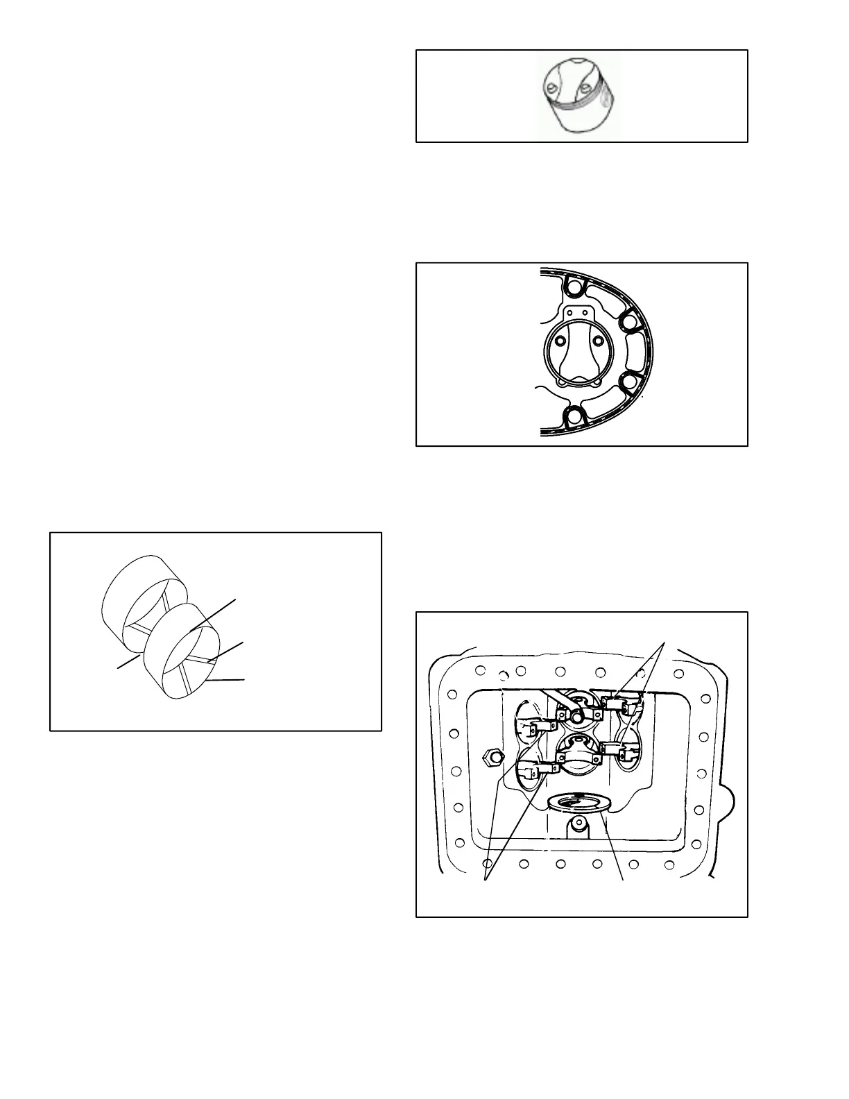
b. Install the piston and rod assemblies up through the
bottom of the crankcase and into the cylinders. Allow
pistons to extend beyond the top of the cylinder to en-
able installation of piston rings. Pistons must be
installed so that the chamfer, on the connecting rod,
faces toward the crankshaft journals. Center rods on
each crankshaft throw may be installed in either
direction. (See Figure 3-17)
CHAMFERED EDGE
CHAMFERED EDGE
SEAL END
THRUST WASHER
Figure 3-17. Installing Piston Rod Assemblies and
Seal End Thrust Washer