Section 11: REAR AXLES
PA1562
4
1.4.3 Speed Sensors (Anti-Lock Brake
system, ABS)
For removing and installing the drive axle speed
sensors (for anti-lock brake systems, ABS), refer
to Section 12: ‘’Brake and Air System’’ and to
Rockwell WABCO Maintenance Manual: “Anti-
Lock Brake Systems For Trucks, Tractors and
Buses", annexed at the end of section 12.
1.5 REMOVAL AND REINSTALLATION
The following procedure deals with the removal
of the drive axle assembly and its attachments
as a unit. The method used to support the axle
during removal and disassembly depends upon
local conditions and available equipment.
1. Raise vehicle by its jacking points on the
body (fig. 5 or see Section 18, "Body" under
heading "Vehicle Jacking Points"). Place jack
stands under frame. Remove drive axle
wheels (if required, refer to Section 13,
"Wheels, Hubs And Tires".
FIGURE 5: JACKING POINTS ON FRAME 18618
2. Exhaust compressed air from the air supply
system by opening the drain cock on each
air reservoir.
3. Disconnect the propeller shaft as directed in
Section 9, "Propeller Shaft", in this manual.
4. On both sides of the vehicle, unscrew
fasteners retaining front wheel housing plastic
guards, and remove them from vehicle.
5. Disconnect both height control valve links
from air spring mounting plate brackets then
move the arm down to exhaust air
suspension.
6. Remove cable ties securing the ABS cables
(if vehicle is so equipped) to service brake
chamber hoses. Disconnect the ABS cable
plugs from the drive axle wheel hubs.
NOTE
When removing drive axle, if unfastening cable
ties is necessary for ease of operation,
remember to replace them afterwards.
7. Disconnect the brake chamber hoses.
NOTE
Position the hoses so they will not be damaged
when removing the axle.
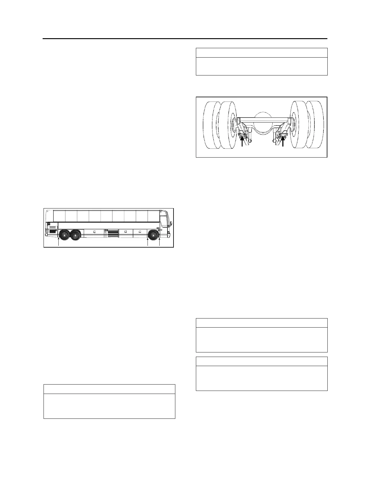
8. Install jacks under the axle jacking points to
support the axle weight (refer to figure 6).
FIGURE 6: JACKING POINTS ON DRIVE AXLE 11005
9. Remove the four shock absorbers as
outlined in Section 16, "Suspension" under
heading "Shock Absorber Removal".
10. Remove the sway bar.
11. Remove the lower and upper longitudinal
radius rod supports from vehicle sub-frame
as outlined in Section 16, "Suspension",
under heading "Radius Rod Removal".
12. Remove the transversal radius rod support
from the vehicle sub-frame.
13. Remove the two retaining nuts from each of
the four air bellows lower mounting
supports.
14. Use the jacks to lower axle. Carefully pull
away the jacks axle assembly from
underneath vehicle.
15. Reverse removal procedure to reinstall drive
axle.
NOTE
Refer to Section 16, “Suspension” for
suspension components' proper tightening
torques.
NOTE
Refer to section 13 "Wheels, Hubs And Tires"
for correct wheel bearing adjustment
procedure.
1.6 DISASSEMBLY AND REASSEMBLY
Disassembly and re-assembly procedures are
covered under applicable headings in Meritor's
"MAINTENANCE MANUAL, NO. 5", annexed to
this section.