Fig. 17
Replacing and Setting the Switch (222) and the
potentiometer (232)
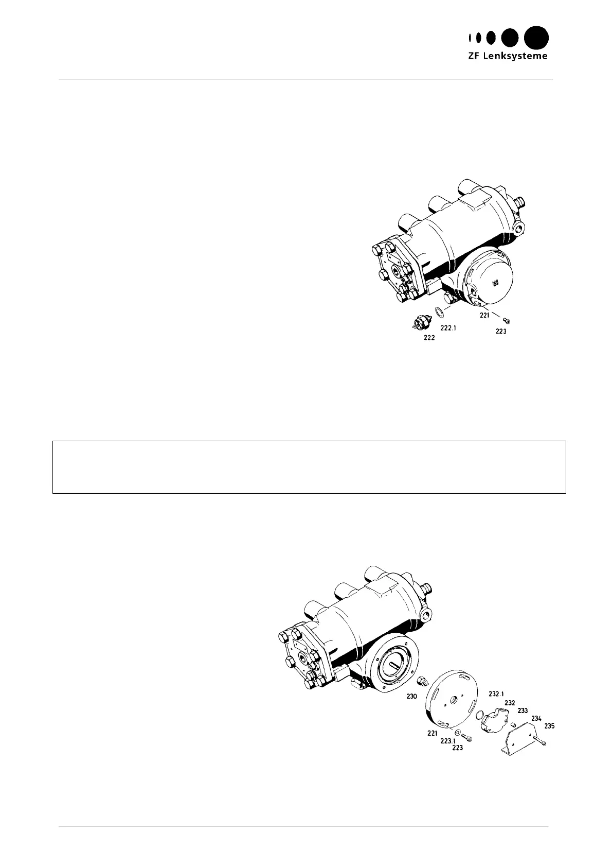
Fig. 18
Instructions on Design, Operation, Maintenance and Inspection
23
V. Replacing and setting the switch (222) and the
p
otentiometer (232)
1 Replacing the switch (222)
Unscrew the switch (222) and replace it
by a new one (tightening torque: 50 Nm).
Starting from mid-position, rotate the
steering gear to the left and to the right.
The contact of the switch (222) must open
after drop arm travels of 5
°
(±1
0%), each
(110
°
± 10% drop arm travel correspond-
ing to 0.3 steering wheel turns) (Fig. 17).
Make sure that the steer angles to the left
and to the right are uniform. If required,
correct the symmetry of the switching
range by rotating the cover (221).
Tightening torque:
Cap screws (223): 5.5 Nm
Testing tool: Multimeter
Note:
The switching range is set by varying the screw-in depth of the switch (222). Washers (222.1) of
different thicknesses are available to enable this setting.
Do not use more than 3 washers (222.1) for the setting operation. (A washer thickness of approx.
0.25 mm corresponds to a drop arm travel of 1
°
- 22
°
at the steering wheel).
T
he cover (221) must be filled with 50 cm
3
of oil (see list of lubricants TE-ML 09).
2 Replacing the potentiometer
2.1 Removing the potentiometer (232)
Rotate the steering gear to mid-position.
Clean the area surrounding the potentiometer (232) (Fig. 18).
Mark the position of the potentiometer (232).
Unscrew the cap screws (235).
Remove the potentiometer (232) along with the screen-
ing plate (234), the spacing sleeves (233) and the O ring (232).