Replacing and Setting the Switch (222) and the
potentiometer (232)
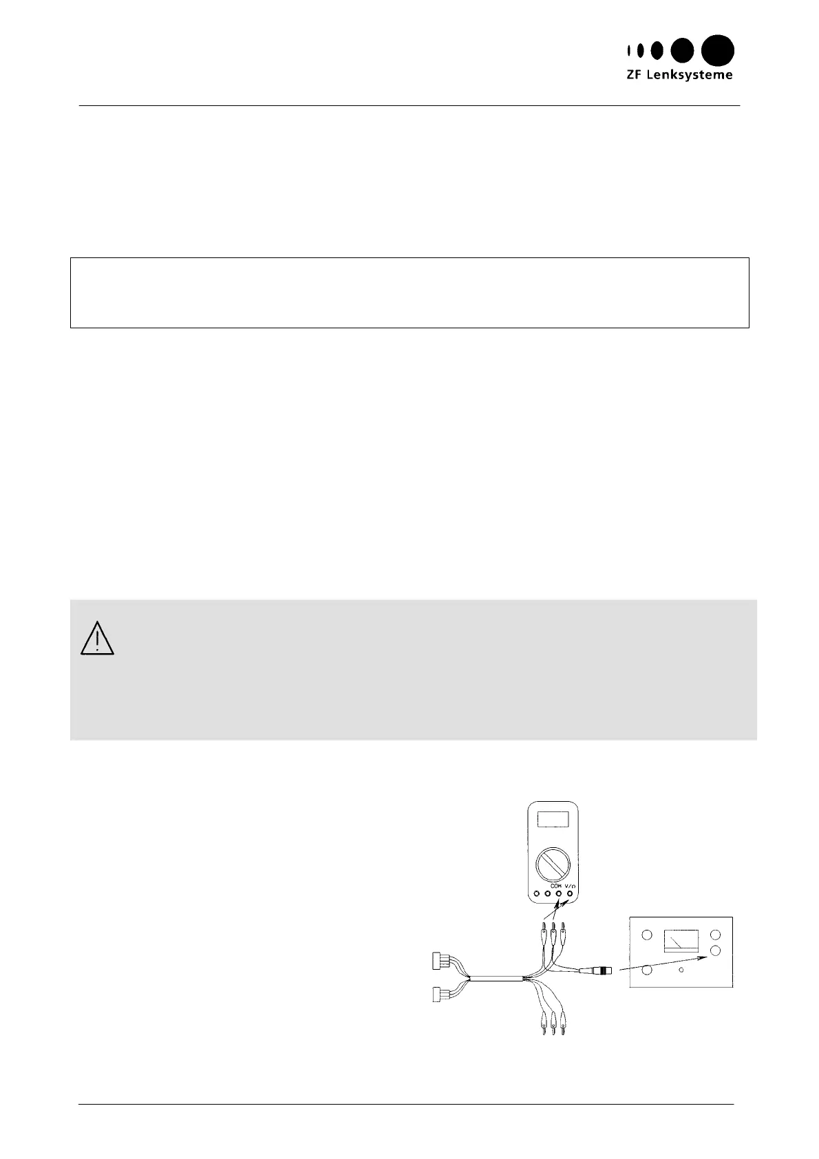
Fig. 19
Tool [6]
Cable colour
black
Cable colour
white
red
blue
red
blue
g
reen
green
Tool [7]
5 V
24 Instructions on Design, Operation, Maintenance and Inspection
2.2 Fitting the potentiometer (232) again
C
heck whether the steering gear is in mid-position.
Fit an O ring (232.1) to the potentiometer (232).
Place the deep groove of the potentiometer (232) drive on the carrier (230).
Note:
The slider of the potentiometer (232) being spring-loaded, it will return to its initial position when
disassembled.
Therefore, check whether the potentiometer (232) can be turned through 50
°
minimum to either
si
de when the steering gear is in mid-position.
Fasten the potentiometer (232) along with the spacing sleeves (233), the screening plate (234)
and the cap screws (235).
Tightening torque: 2.8 Nm
Check:
The installed position of the potentiometer (232) must be identical with the position as marked
during disassembly.
2.3 Setting the potentiometer (232)
Attention:
A maximum value of 6 V must not be exceeded for otherwise the potentiometer (232) would be
destroyed.
The tumbler switch of the Servotronictest tester (tool [7]) must not be switched to speedo position
as otherwise the potentiometer would be destroyed.
Rotate the steering gear to mid-position (dividing the total number of steering wheel turns in two).
Setting a voltage of 5V
Connect tools [6] and [7] (or use a suitable
transformer) and the Multimeter measuring
instrument as shown in Fig. 19 .
Switch the tumbler switch of the Servotronic-
test tester (tool [7]) to transducer position.
Continue adjusting the transducer regulator
until the Multimeter measuring instrument
reads 5V.