Replacing and Setting the Switch (222) and the
potentiometer (232)
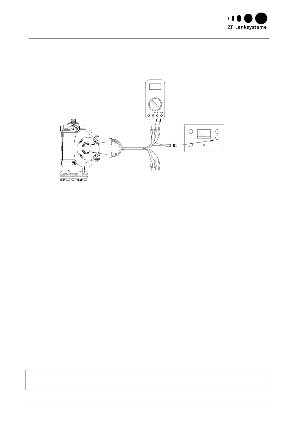
Fig. 20
Tool [6]
C
able colour
black
Cable
colour
white
red
blue
green
red
blue
green
Tool [7]
Instructions on Design, Operation, Maintenance and Inspection
25
S
etting the potentiometer (232) to steering gear mid-position
Connect tools [6] and [7] and the Multimeter measuring instrument as shown in Fig. 20.
Rotate the potentiometer (232) together with the cover (221) until the Multimeter measuring instru-
ment reads half the voltage applied, namely 2.5 V + 0.03 V.
In this position, tighten the cap screws (223) (tightening torque: 4+1.5 Nm).
Instructions on measurements, paths 1 and 2
Measurement, path 2:
See Fig. 20
Measurement, path 1:
See Fig. 20
Additionally: Plug in a jumper from blue to blue
P
lug in a jumper from red to red
Unplug the green cable of path 2
At variance: Plug the green cable of path 1 in the Multimeter
Rotate the potentiometer (232) along with the cover (221) until the same voltage (specified value:
2.3...2.7 V) is indicated for both paths.
In this position, tighten the cap screws (223) (tightening torque 4 +1.5Nm).
Rotate the steering gear to the right-hand lock and measure the voltages of paths 1 and 2
(specified value: 0.122 V...4.88 V).
Rotate the steering gear to the left-hand lock and, again, measure the voltages of paths 1 and
2 (specified value: 0.122 V...4.88 V).
Note:
If the specified values are not attained, a new potentiometer has to be used.