Section 3
Compressor Replacement
Copyright 2002 Maintenance Manual MM-0204
Page 10 ArvinMeritor, Inc. Issued 08-02
Compressor Installation
1. Reinstall the oil supply tube.
2. Install a new compressor gasket.
3. Position the compressor on the engine.
4. Install the three flange mounting bolts. Tighten
to 15 lb-ft (20 N•m) +90° rotation.
5. Install the two bolts that hold the bracket to
the compressor and the two bolts that hold the
bracket to the engine block. Run the bolts
down finger tight at both ends of the bracket
(engine and compressor). The bracket should
be in contact with both surfaces; engine block
and compressor rear support face. Tighten
bolts to 18 lb-ft (25 N•m) maximum at
compressor side. Tighten bolts at engine side
per Mack specification.
6. Attach the discharge and coolant fittings.
Finger-tighten fittings and rotate 2 to 3 turns
to position fitting.
7. Connect all air and water lines leading to the
compressor. Tighten per Mack specifications.
8. Add engine coolant to the cooling system. Use
the coolant recommended by the engine
manufacturer. Visually inspect the engine and
compressor for leaks.
9. Start the engine and allow air system to build
to governor cutout. Stop the engine. Use a
soap and water solution at connection points
to check for air leaks. Make any necessary
repairs.
10. Remove the wheel blocks and release the
spring (parking) brakes.
Cylinder Head Replacement
Removal
1. Follow the steps listed in Compressor
Removal to remove the compressor from the
engine. Take care not to damage the
crankcase, since it will not be replaced.
2. Use a cleaning solvent to remove road dirt and
grease from the exterior of the compressor.
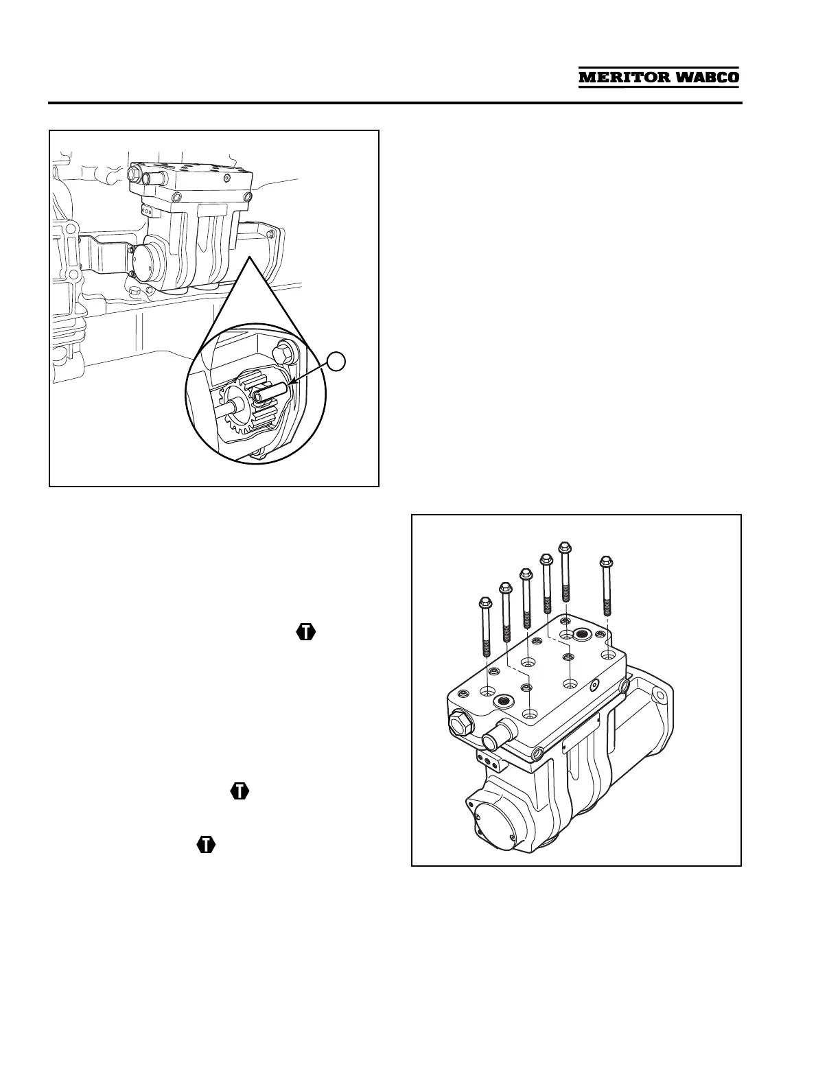
3. Remove and discard the six hex head bolts
that attach the cylinder head to the crankcase
and remove the cylinder head valves and
gaskets.
Figure 3.3
.
4. Use a mild cleaning solvent to clean the top of
the crankcase.
Figure 3.2
1 OIL SUPPLY TUBE
4000263b
4000268d
1
Figure 3.3
4000269b