Section 16: SUSPENSION
PA1562
10
CAUTION
It is extremely important upon reconnection of
the rods that the proper clearance height
between the axle and body be maintained.
Otherwise, the rubber bushings in radius rod
ends will become preloaded, thus reducing
their life span.
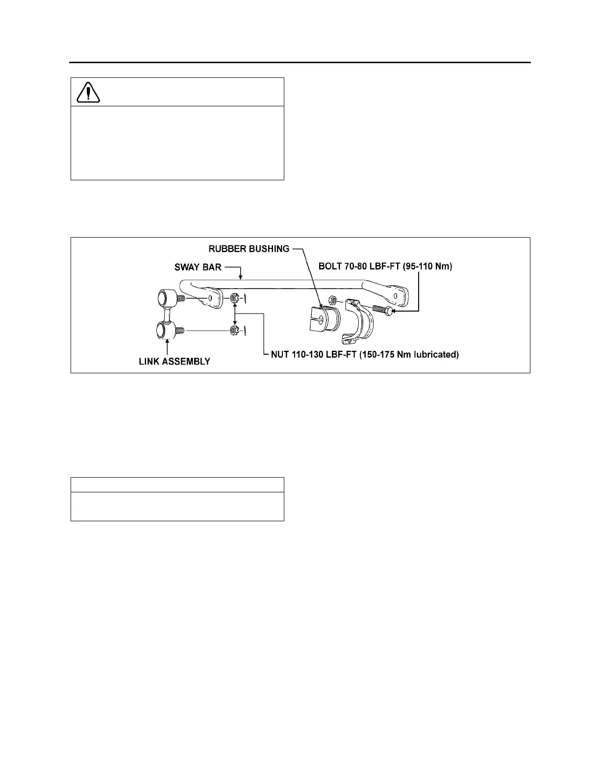
2.4 SWAY BAR
A sway bar is provided on the front axle to increase vehicle stability. It controls lateral motion (swaying
movement) of the vehicle (Fig. 10).
FIGURE 10: I-BEAM FRONT AXLE SWAY BAR 16099
2.4.1 Removal
1. Disconnect the two links from sway bar.
2. Safely support the sway bar. Unbolt the four
bushing collars from subframe.
3. Remove sway bar.
NOTE
Sway bar bushings are slitted to ease their
removal.
2.4.2 Installation
1. Loosely install the sway bar.
2. Tighten the eight bushing collar nuts to 70 -
80 lbf-ft (95 - 110 Nm) (Fig. 10).
3. Install two sway bar link upper and lower
nuts and tighten to 100 - 130 lbf-ft (150 -
175 Nm) (Fig. 10).
4. Install a cotter pin on each nut and bend.
3. INDEPENDENT FRONT SUSPENSION (IFS)
3.1 STEERING LINKAGE
Turning motion of the steering wheel is transferred by the steering gear and steering linkage to the
steering arms at the right and left front wheels. The steering linkage consists of tie rods connected to the
bell crank and the steering arm at the left side of the coach, and to the idler arm and steering arm at the
right side of the coach. The bell crank and idler arm are connected by a relay rod. A drag link connected
to the bell crank and the pitman arm, which is mounted to the steering gear, transfers the turning motion
of the steering wheel to the steering arms (Fig. 11).
Lower and upper A-arms are widely spaced. They are mounted on ball joints. Torque rods prevent
rotation of the uprights around the lower and upper ball joints.
If the steering linkage is bent, twisted or worn, steering action of the coach will be seriously affected. Any
time steering linkage components are replaced or adjusted, steering geometry and front wheel alignment
must be checked as explained in this section.