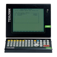
Appendix B: Port Pinouts And Cable Diagrams
8255/60 Peripheral Port I/O Connector
(28-Pin PCR)
B-2 Teklogix 7035, 8255 & 8260 Terminals User Manual
B.2 8255/60 Peripheral Port I/O Connector (28-Pin PCR)
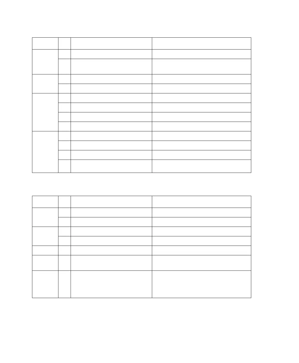
Scanner
Power
17 5V_SCAN_PWR 5 V scanner power (duplicate of pin 18).
18 5V_SCAN_PWR/TX_KEY
5 V scanner power/transmit monitor
signal for radio test.
19 EXP0 Expansion 0.
20 CV_OUT Control voltage output.
Radio
Test
21 EXP1 Expansion 1.
22 EXP2 Expansion 2.
23 EXP3 Expansion 3.
24 EXP4 Expansion 4.
Serial
Port 1
(COM1)
25 RTS1 Request-to-send (output) RS-232D.
26 CTS1 Clear-to-send (input) RS-232D.
27 SERIAL1_TX Serial transmit data RS-232D.
28 SERIAL1_RX Serial receive data RS-232D.
Function Pin Signal Name Description
Ground
1 GND Digital ground.
2 GND Digital ground.
Audio
3 MIC Microphone input.
4 LINE_OUT Line level audio output
Alarm 5 BEEP External beeper output.
EMI
Shield
6 SHIELD Digital ground.
Diagnos-
tic Mode
7 DIAG
Input. If grounded at power up, causes
terminal to enter diagnostic mode. Menu
allows flash-ROM upgrade and other test
modes.
Function Pin Signal Name Description