Operation
62 Rev. B4 Feb 2015 CS210
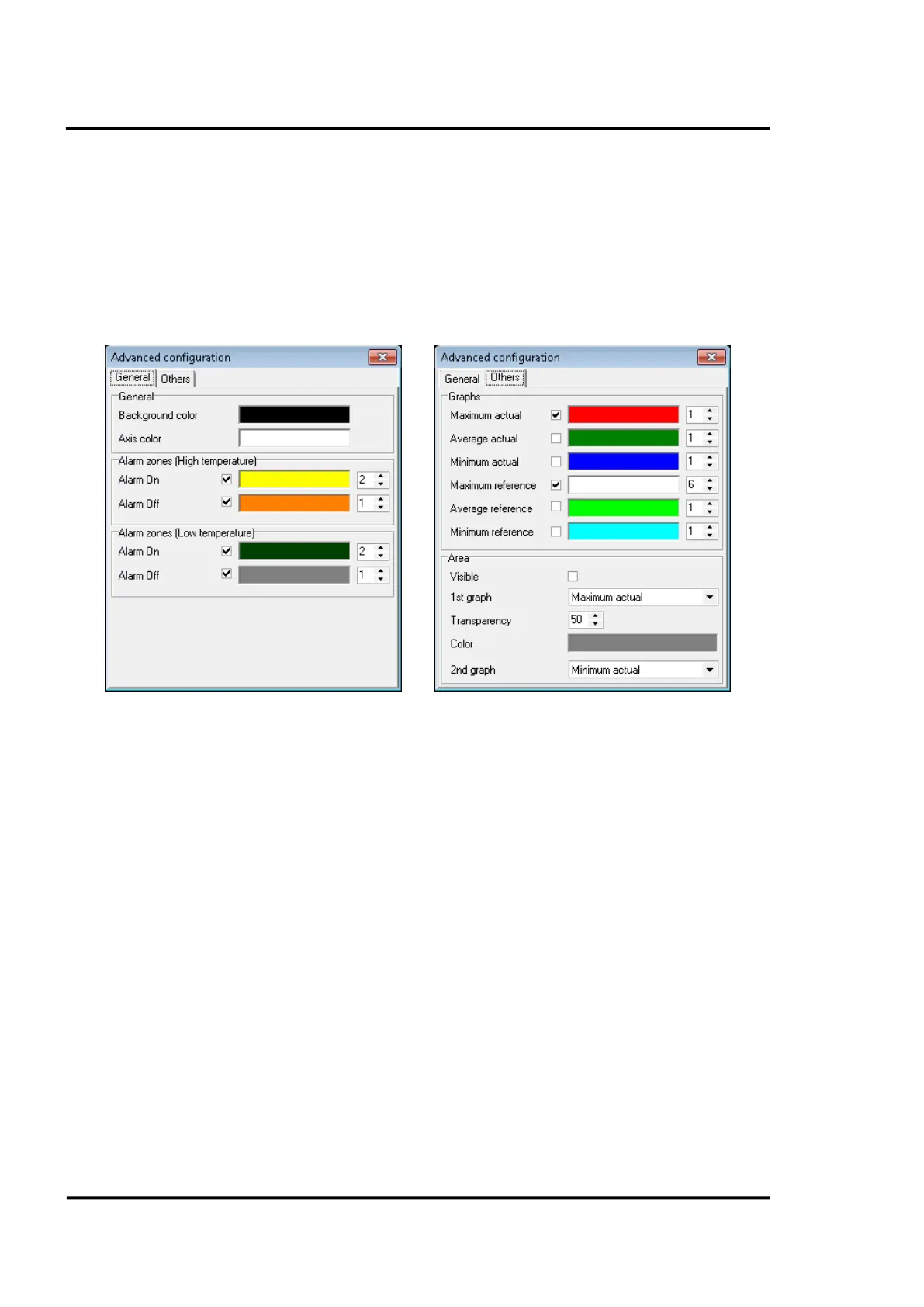
In the context menu (right mouse click) of the temperature chart view you can access the <Set as
reference> item which defines the current thermal image as a reference image. A reference image will
be used for calculating difference images, see section 7.2.13 <Graphic> <Difference between images>,
page 75.
In the same context menu you can access the <Advanced configuration> item. It allows the user to
select between different display options: background and axis colours, colours for the alarm zones,
profile lines (formats, colour and thickness) and under <Area> the configuration of an envelope as the
difference curve between two temperature graphs.
Figure 61: Advanced configuration for the Real Time view
In the middle part of the view, you will find the illustration for the refractory zones of the kiln. Each
zone is mouse-sensitive, providing a tool tip with the most essential information for that zone. The
<K> symbol indicates the kiln trigger. If the LRM life ring migration is installed, the additional
position indicators are marked as consecutive numbers starting with <1>, <2> and so on.
The thermogram takes up most of the lower screen area, and represents the temperature distribution
across the kiln surface as a false-color image. The context menu entry <Continuous View> allows you
to toggle between the approaches to update the view: either immediately with each new incoming line
from the scanner or only when kiln rotation is completed. You can also superimpose the thermogram
with symbols for the position of the linescanners <S> and the shadow pyrometers <P>.
The lower status bar makes it possible to see other useful information without the need to open other
windows. The range of information shown is:
• Time taken to complete the displayed lap
• Time elapsed since the lap was displayed
• Location and temperature at the cursor location in the current thermogram
• Internal temperatures of the temperature sensors (Scanners and pyrometers)
• Burning zone temperature