Because RFL™ and Hubbell® have a policy of continuous product improvement, we reserve the right to change designs and specifications without notice.
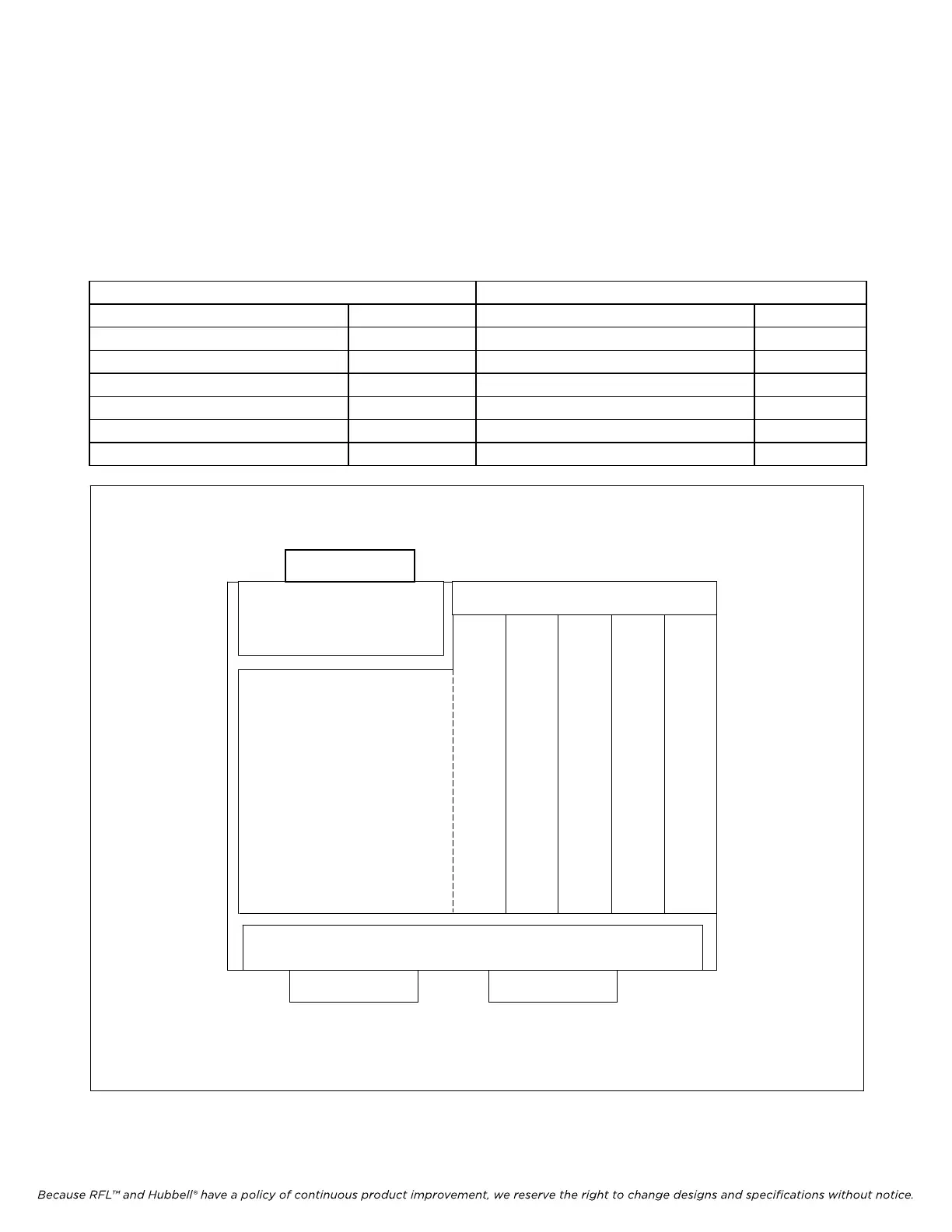
9.3 MODULE PLACEMENT IN THE RF CHASSIS (50W SYSTEMS)
50 Watt systems are housed in a 6U high chassis. The upper part of the chassis is the RF Section, and
the lower part of the chassis is the RFL 9780/85. Module placement in the RF Chassis is shown in
Table 9-5, and Figures 9-2, and 9-15. A Typical RF Chassis will have modules installed as indicated in
Figure 9-15.
Table 9-5. Module Placement In RF Chassis (50W System)
Front Panel Modules Rear Panel Modules
50W Power Amplifier 9.3.1 Mother Board 9.3.8
Tx Filter 9.3.2 Power Amplifier Power Supply 9.3.9
Balance Board 9.3.3
Line Board 9.3.4
Rx Filter 9.3.5
Rx Connection Board 9.3.6
Attenuator 9.3.7
POWER AMP
POWER SUPPLY
MOTHER BOARD
50W POWER AMPLIFIER
TX
FILTER
BAL-
ANCE
BOARD
LINE
BOARD
RX CONNECTION BOARD OR
RX FILTER
ATTEN-
UATOR
PART OF
TX FILTER
REAR
FRONT
Figure 9-15. Module Placement in a Typical RFL 9508 RF Chassis (Top View)
RFL 9785 RFL Electronics Inc.
May 16, 2011 9-19 (973) 334-3100