Because RFL™ and Hubbell® have a policy of continuous product improvement, we reserve the right to change designs and specifications without notice.
Table 9-8. Function of jumpers, connectors and potentiometers on Power Amp.
Reference Component Function
Designation
DS1 LED (green) This LED is located on the front left panel of the Power Amplifier. The LED is lit when
the Power Amplifier is transmitting.
J1 connector Provides input dc voltage from power supply, +92Vdc and +30Vdc.
J2 connector Power output to Tx Filter Module.
J3 connector Power amplifier failure alarm output signal. Signal goes to alarm relay on balance
board, which provides form-C contacts on back of RF chassis. Output is +12Vdc when
power amp fails.
J4 connector Tx In (RF input signal from back of MA-650)
J5 connector Spare Tx In (not used)
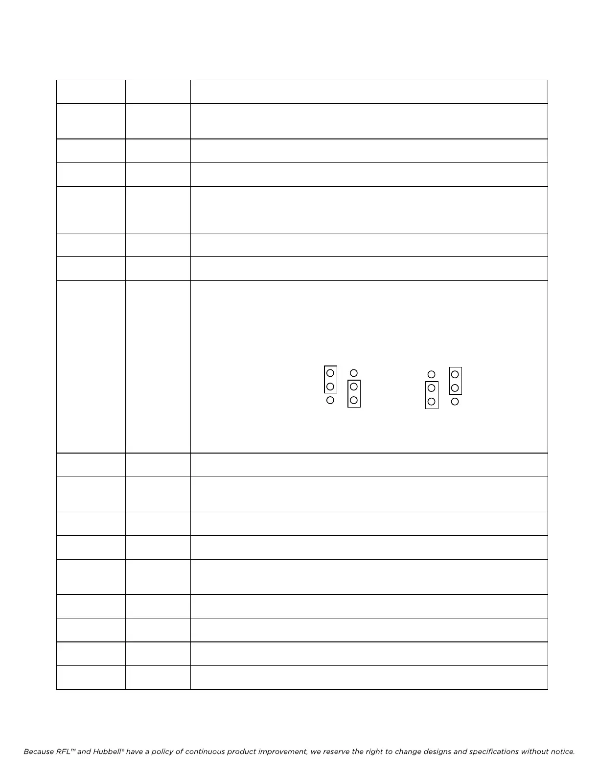
J6 & J7 jumpers These are Phase Jumpers used in 100W applications, which set the outputs of the two
50W amplifiers 180 deg out of phase. This will insure that the total output power is
additive. In 50W applications, J6 and J7 can be set either way. In 100W applications,
one 50W amp must be set to “A” and the other 50W amp must be set to “B”. As a
standard, set the Main 50W amplifier to “A” and the Auxiliary 50W amplifier to “B” as
shown below.
RFL 9785 RFL
Electronics Inc.
J6 J7
Setting “B”
J6 J7
Setting “A”
J8* jumpers For factory use only. Should always be set to position B.
J9* jumpers For factory use only. Determines if output disconnect relay is used.
For use with ON-OFF carrier set to B.
For all other applications set to A.
J10* jumpers For factory use only. Should always be set to Insert.
R8 potentiometer Sets the low input RF signal threshold at J4
R14 potentiometer Sets the idle current, which is the power that the power amp draws from the power
supply with no load and no input signal.
R69 potentiometer Balances the RF output signal
R74 potentiometer Over current RF output adjustment
R83 potentiometer RF output power level adjustment.
R163* potentiometer For factory use only.
* Effective October 2010
May 16, 2011 9-26 (973) 334-3100