Because RFL™ and Hubbell® have a policy of continuous product improvement, we reserve the right to change designs and specifications without notice.
Line
Coupling
Equipment
Digital
Transmitter
10 Watt
Power
Amplifier
Output
Filter
Logic
Module
Detector
Narrow
Band
Filter
Receiver
Downshifter
SOE/IRIG-B
(optional)
Start
And
Stop
Inputs
Block
And
Alarm
Outputs
RS-232
Digital
Level Mete
Checkback
(optional)
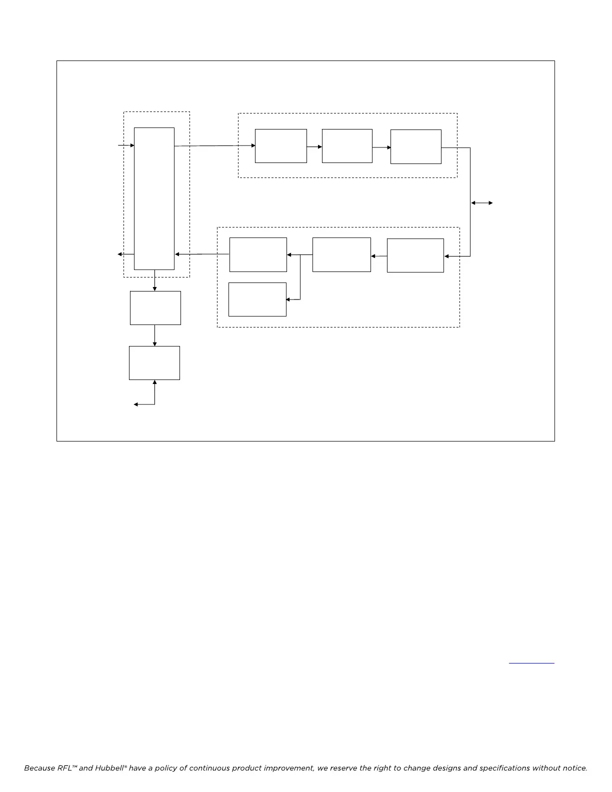
Figure 2-2. Typical block diagram of RFL 9785 chassis
2.7 RFL 9785 SUBASSEMBLIES
Each RFL 9785 terminal contains several circuit board modules and I/O modules. Paragraphs 2.7.1
through 2.7.12 describe the different modules used in the RFL 9785 terminal.
2.7.1 AM LOGIC MODULE
The 9785 AM Logic Module monitors the CARRIER START, CARRIER STOP, and RESERVE KEY
keying inputs, as well as signals from other modules of the RFL 9785. It uses this information to
generate command signals for the transmitter and receiver detector modules. Switches SW1-1 through
SW1-7 on the 9785 AM Logic Module allows the logic to be set according to the requirements of the
specific application. The 9785 AM Logic Module also provides status information for the Sequence of
Events Module. Additional information on the RFL 9785 AM Logic Module can be found in Section 6
of this manual.
RFL 9785 RFL Electronics Inc.
June 18, 2009 2-7 (973) 334-3100