Because RFL™ and Hubbell® have a policy of continuous product improvement, we reserve the right to change designs and specifications without notice.
Section 6. AM LOGIC MODULE
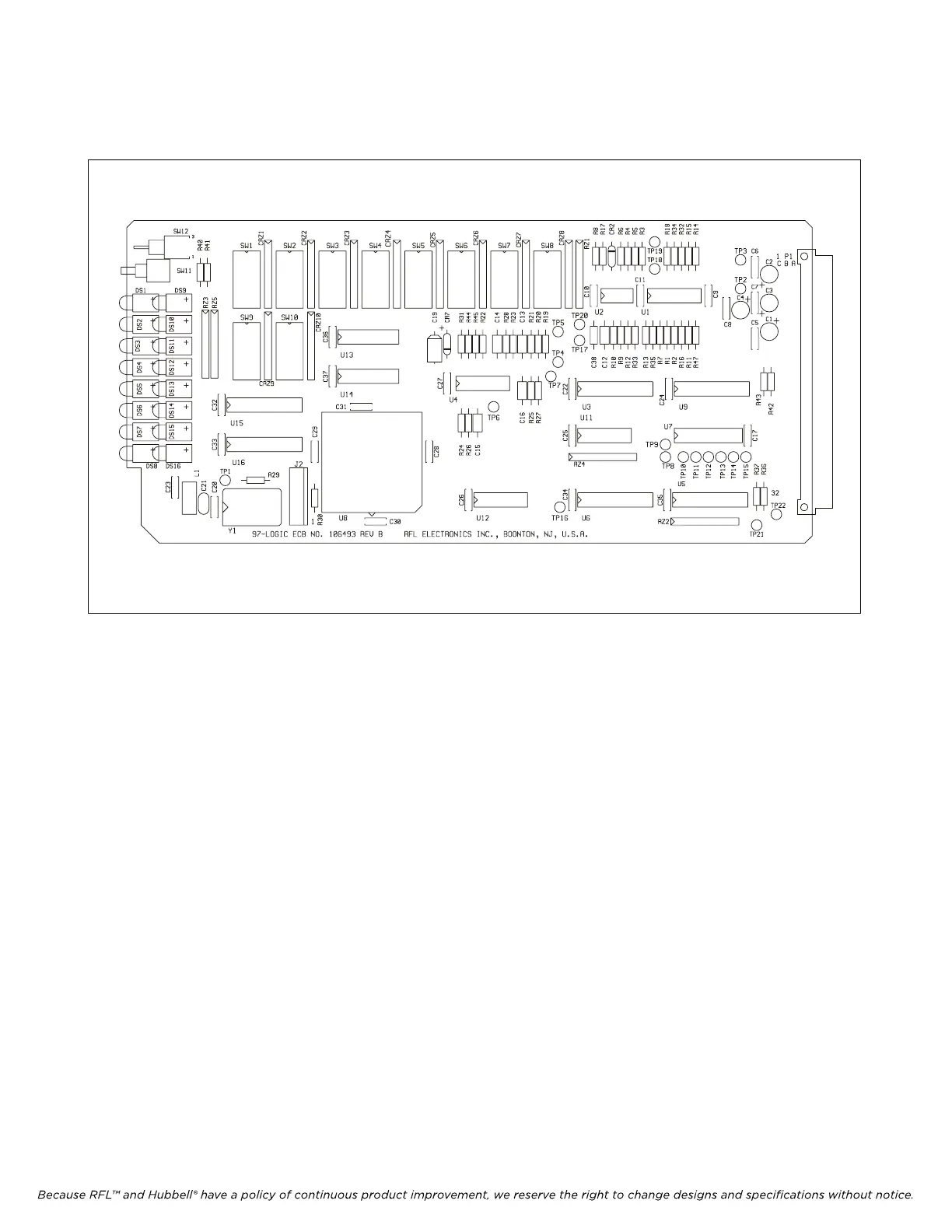
Figure 6-1. RFL 9785 AM Logic Module
6.1 DESCRIPTION
The 9785 AM Logic Module (Figure 6-1) monitors the CARRIER START, CARRIER STOP, and
RESERVE KEY keying inputs, as well as signals from other modules of the RFL 9785. It uses this
information to generate command signals for the transmitter and receiver detector modules. Switches
SW1 and SW2 on the 9785 AM Logic Module allows the logic to be set according to the requirements
of the specific application. The 9785 AM Logic Module also provides status information for the
Sequence of Events Module (SOE).
The 9785 AM Logic Module has eight red indicator lamps (DS1 through DS-8) on the front edge of
the module, which protrude through the front panel of a closed chassis for ease of visibility. These
include RX DETECT (DS1), BLOCK OUT (DS2), START (DS3), STOP (DS4), RESERVE (DS5),
REMOTE INIT (DS6), TX CARRIER (DS7), and TX FAIL (DS8).
Open-collector transistors are provided on the 9785 AM Logic Module to drive relays with block,
logic alarm, and transmitter fail alarm output signals.
For specific component information at the board level please contact the factory with the board
part number and revision level. AM Logic Module Schematics are provided at the end of this section.
RFL 9785 RFL Electronics Inc.
February 7, 2007 6-1 (973) 334-3100