Because RFL™ and Hubbell® have a policy of continuous product improvement, we reserve the right to change designs and specifications without notice.
NOTE
Any
device connected to the front-panel RS-232 connector mu
st drive the DTR line high. This
will disable the rear-panel RS-232 port, eliminating any conflict that may arise from two users
attempting to access the RFL 9785 at the same time. Most ports drive the DTR line high.
2
3
5
2
3
5
3
2
7
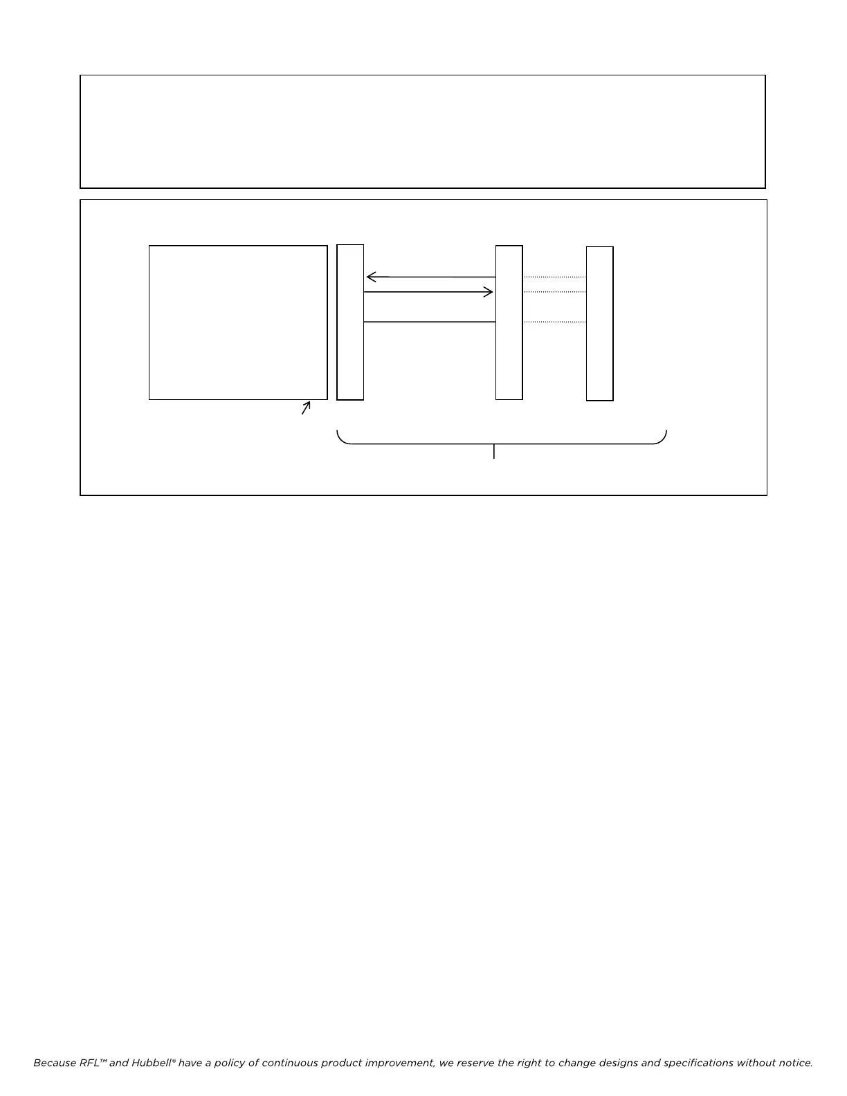
Not used 1
Receive Data (RxD) (input) 2
Transmit Data (TxD) (output) 3
Not Used 4
Signal Common 5
Not Used 6
Not Used 7
Not Used 8
Not Used 9
9785 REAR CONNECTOR TO RFL 9660 OR MODEM
Male DB-9 Female DB-9 Female DB-25 Female
Cable Assembly
Figure 14-2. Making connections from the PC to the RFL 9785 rear connector
14.2.2 COMMUNICATIONS INFORMATION
The serial communications port on the terminal or PC must be configured to match the 9785:
Data Bits 8
Stop Bits 1
Parity None
Baud Rate 9600 baud
Handshaking XON/XOFF
The terminal (or PC terminal emulation mode) must support either ANSI or VT-100 control codes for
cleanest visual presentation.
14.3 VIEWING APRIL COMMANDS
Once you have connected a terminal or PC to the RFL 9785 (either directly or through an RFL 9660
Digital Switch) and pressed the [ENTER] key the RFL 9785 will send the following prompt to your
terminal:
9785>
This means that you have accessed the RFL 9785, and can now use APRIL commands to view lists of
parameter settings, alarm conditions, and other information. To view a list of the APRIL commands,
press the [H] and [ENTER] keys:
RFL 9785 RFL Electronics Inc.
April 25, 2005
14-2 (973) 334-3100