Because RFL™ and Hubbell® have a policy of continuous product improvement, we reserve the right to change designs and specifications without notice.
6.4 CONTROLS AND INDICATORS
Figure 6-3 shows the locations of all controls and indicators on the AM Logic module. These controls
and indicators are described in Table 6-1. LEDs DS1, DS2 and DS4 through DS7 are visible with the
module installed in the chassis. All other controls and indicators are only accessible when the module
is removed from the chassis or is on a card extender.
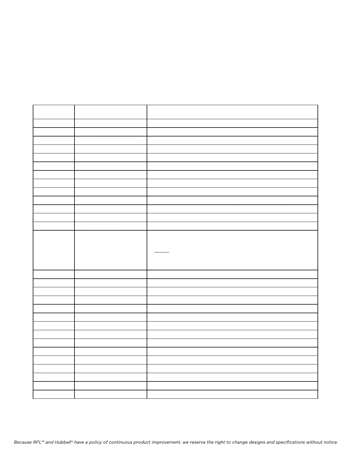
Table 6-1. Controls and indicators, RFL 9785 AM Logic Module
Component
Designator
Name/
Description
Function
DS1 LED Indicator, red Lights when a received signal has been detected
DS2 LED Indicator, red Lights when a block condition has been detected
DS3 LED Indicator, red Lights when the CARRIER START input is active
DS4 LED Indicator, red Lights when the CARRIER STOP input is active
DS5 LED Indicator, red Lights when the RESERVE input is active
DS6 LED Indicator, red Lights when the REMOTE INIT input is active
DS7 LED Indicator, red Lights when the TX CARRIER is active
DS8 LED Indicator, red Lights when the power amplifier has failed
DS9 to DS16 LED indicators Not installed
SW1 DIP Switch See Table 6-2.
SW2 DIP Switch See Table 6-4.
SW3 to SW10 DIP Switch Not installed
SW11 Push button switch Not installed
SW12 Toggle Switch Test switch used to manually key the transmitter module during setup
and alignment as follows:
SW12
UP Enabled (initiates local carrier)
DOWN Disabled
TP1 Test point Monitoring point for 3.584 MHz master clock for ACTEL
TP3 Test point Ground
TP4 Test point Monitoring point for carrier detect signal
TP5 Test point Monitoring point for reserve keying input signal
TP6 Test point Monitoring point for carrier start input signal
TP7 Test point Monitoring point for carrier stop input signal
TP8 Test point Monitoring point for BLK OUT RLY1 logic control signal
TP9 Test point Monitoring point for BLK OUT SS1 logic control signal
TP10 Test point Monitoring point for SPARE DRIVER1 logic control signal
TP11 Test point Monitoring point for BLK OUT SS2 logic control signal
TP12 Test point Monitoring point for SPARE DRIVER2 logic control signal
TP13 Test point Monitoring point for CB (checkback) RELAY logic control signal
TP14 Test point Monitoring point for TX FAIL logic control signal
TP15 Test point Monitoring point for BLK OUT RLY2 logic control signal
TP16 Test point Monitoring point for CARRIER SW OUT logic control signal
RFL 9785 RFL Electronics Inc.
February 7, 2007 6-6 (973) 334-3100