Because RFL™ and Hubbell® have a policy of continuous product improvement, we reserve the right to change designs and specifications without notice.
Section 10. OUTPUT FILTER MODULES
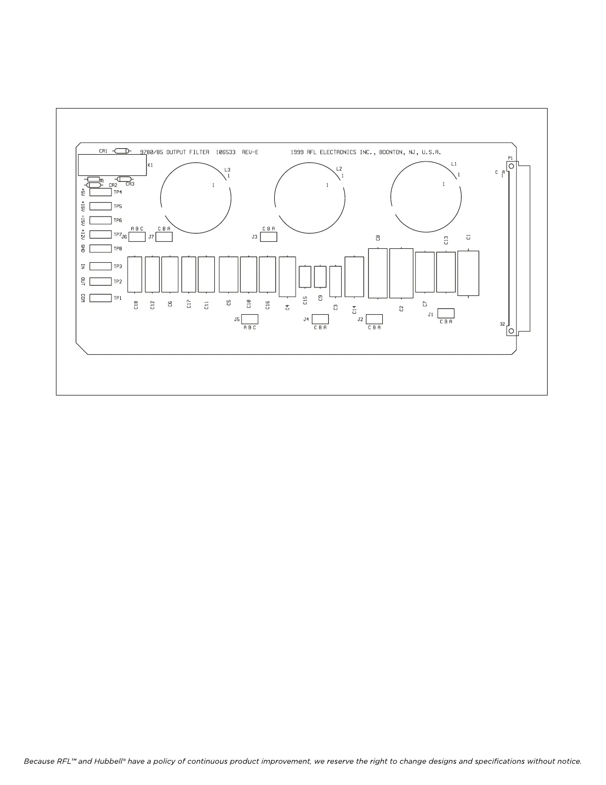
Figure 10-1. Typical RFL 9785 Output Filter Module (without reflected power meter option)
10.1 DESCRIPTION
RFL 9785 Output Filter Modules are used to reduce the harmonic content of the RFL 9785's output
signal to a level that is at least 55 dB below the carrier level. A typical RFL 9785 Output Filter module
appears in Figure 10-1.
The filters are entirely passive and require no input power for operation. The filters are located after
the power amplifier and are designed to pass the rated full power of 10 watts. Due to the physical size
of some of the components used and the required value changes over the selectable frequency ranges
of the RFL 9785, several filter modules are required.
Color coded test points are located on the front edge of the module to monitor power supply voltages
as follows: TP4 (red) +5Vdc, TP5 (orange) +15Vdc, TP6 (yellow) –15Vdc, TP7 (purple) +12Vdc, TP8
(black) ground.
Output Filter Modules 106530-11 through -15 have additional circuitry to sense the impedance
mismatch to the load (reflected power). The reflected power can be read locally or remotely using RFL
Web Commander or Hyper-terminal.
For specific component information at the board level please contact the factory with the board
part number and revision level. Output Filter Schematics are provided at the end of this section.
RFL 9785 RFL Electronics Inc.
June 18, 2009 10-1 (973) 334-3100