Because RFL™ and Hubbell® have a policy of continuous product improvement, we reserve the right to change designs and specifications without notice.
99347 99347
10K
4793
2SC
100UH 2A
100UF
45142-3
.1UF
2SA
1837
100UF
1837
2SA
105186
1 OHM 3W
1 OHM 3W
102757
4793
2SC
1 OHM
1 OHM
MJE182
1K
10 OHM 2W
.0068UF
1 OHM 1W
1 OHM 1W
.33UF
105186
99347
20K
10UF 100V
45142-2
2K
1/2W
2K
.22UF
.22UF
.22UF
4.7K 3W
J1
R163
J10
J4 J5 R83 R69 J6 J7
R14
R8
J2
R74
J8
J9
J3
DS1
SW1
SW2
Top View
Switch Block Typical
ON
1234
SW2
5678
RFL 9785 RFL Electronics Inc.
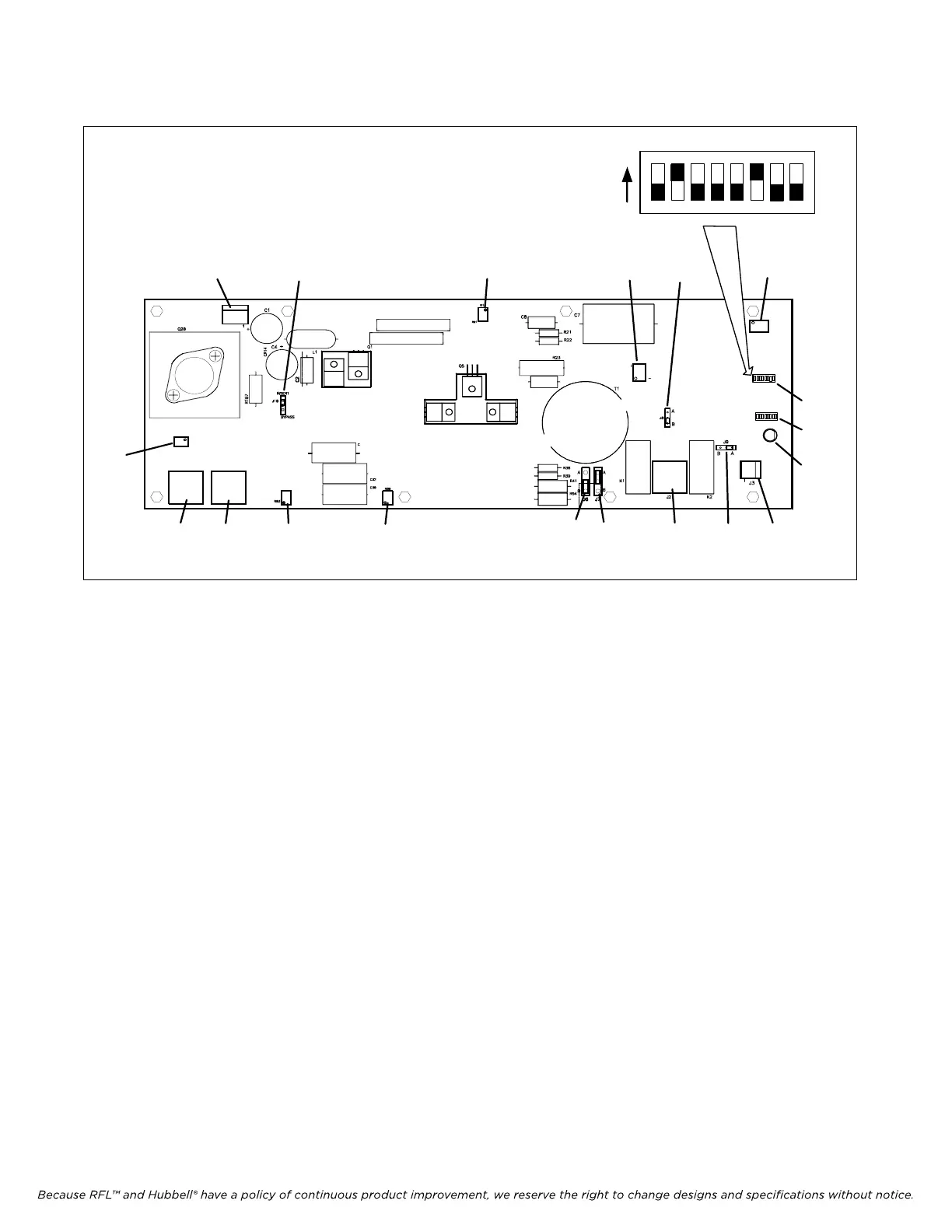
Figure 9-18. Circuit board of 50W Power Amp, locations of jumpers, connectors, switches and potentiometers.
As shown above; effective October 2010, two switch blocks have been added to the Power Amplifier
Circuit Board. These DIP switches are factory set to protect the circuit board from overvoltage or
excessive phase angle situations. See Table 9-9 for a description of the switch settings.
If the protective circuits are activated the Power Amplifier will shut down for approximately 2.5
seconds and then come up for 25ms. This pattern will continue until the safety parameters are met and
the condition cleared.
May 16, 2011 9-25 (973) 334-3100