Because RFL™ and Hubbell® have a policy of continuous product improvement, we reserve the right to change designs and specifications without notice.
Section 22. SIMPLIFIED COMMISSIONING PROCEDURE
And FUNCTIONAL TEST PROCEDURE
22.1 SIMPLIFIED COMMISSIONING PROCEDURE
1) Check the carrier output level by removing the coax from carrier output to the line tuner.
a) Connect a 50-ohm non-inductive dummy load of sufficient wattage to the carrier output
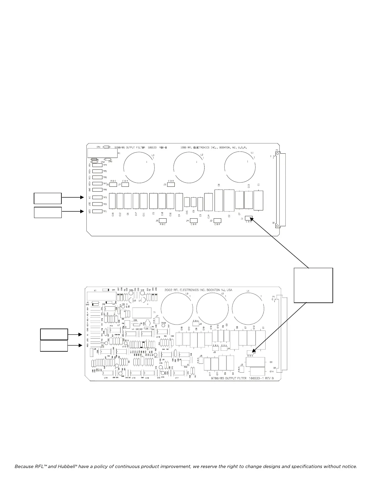
connector. Place the Frequency Selective Volt Meter (FSVM) leads on the Output Filter TP1
(Brown – “COM”) and TP3 (White – “IN”), check for the following level:
2) 10W applications measure 22.36 Vrms (40dbm)
TP1/COM
TP3/IN
hite
RFL 9785 RFL Electronics Inc.
Figure 22-1. Controls and Indicators, 9785 Output Filter Modules
(106530-1 to -5 WI
THOUT RPM Option)
J1
Note: Only for step
Error! Reference
source not found. of
Transm
itter
F
unctional Test
TP1 (COM)
TP3 (IN)
hite
Figure 22-2. Controls and Indicators, 9785 Output Filter Modules
(106530-11 to -15 WITH RPM Option)
March 1, 2013 22-1 (973) 334-3100