Because RFL™ and Hubbell® have a policy of continuous product improvement, we reserve the right to change designs and specifications without notice.
19.5 RF LINE I/O MODULE
1
2
3
4
5
6
7
8
9785 RF LINE I/O
1
2
3
4
J5
TX
J7
RX
TX
RX
EXT METER
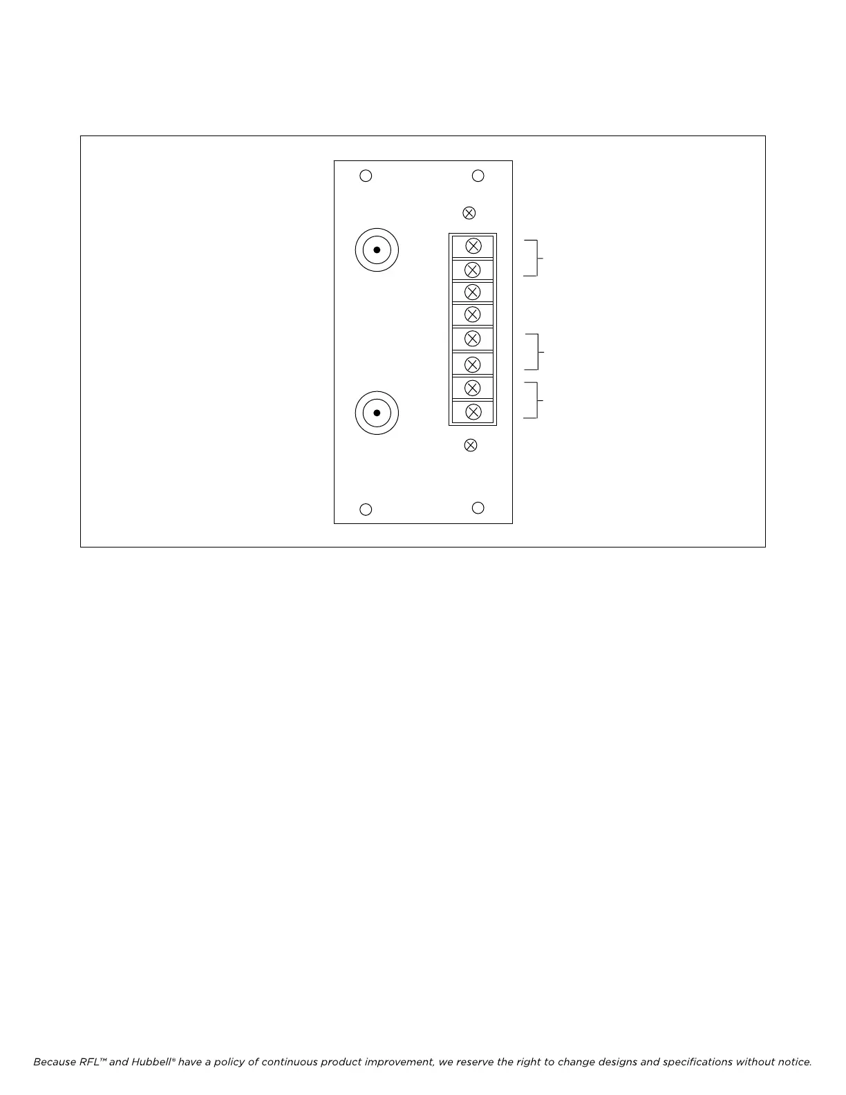
Figure 19-13. RFL Line I/O module, rear panel view
19.5.1 DESCRIPTION
The RF Line I/O module (Figure 19-13) has two UHF connectors with spark gaps, additional
protection circuits and a selectable line termination impedance (50Ω, 75Ω or none). The top port J5, is
for TX signals and the bottom port J7, is for RX signals.
19.5.2 CONTROLS AND INDICATORS
Figure 19-14 shows the location of all controls and indicators on the RF Line I/O module. These
controls and indicators are described in Table 19-6. TB1, J5 and J7 accessible with the RF Line I/O
module installed in the chassis. All others are accessible when the module is removed from the chassis
or is on a card extender.
RFL 9785 RFL Electronics Inc.
September 1, 2006 19-27 (973) 334-3100