Because RFL™ and Hubbell® have a policy of continuous product improvement, we reserve the right to change designs and specifications without notice.
15.5 VOICE FILTER
R1
TP2
U1 C6
C1
R2
R44
U2
U3
U5
R19
R25
R33
R39
R43
TP1
TP3
C4
C5
C7
C9
C8
C3
C11
C10
C12
C17
C16
P1
C22
C23
C24
C29
C25
C26
C31
C30
C19
C32
C27
C28
C35
C34
C13
C14
C15
C18
C21
C33
R3 R4
R7
R8 R9
R10
R11
R12
R13 R14
R15 R16
R18
R17
R21
R20
R22
R23
R24
R27
R28
R26
R34R30
R29
R31
R32
R35
R38
R37
R36
R41
R40
R42
U4
P2
C20
C36
C37
106583 REV B
1999 RFL ELECTRONICS INC
FILTER
97 VOICE
1
1
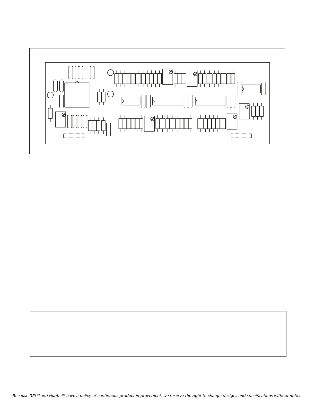
Figure 15-6. RFL 9785 Voice Filter
15.5.1 DESCRIPTION
The Voice Filter (Figure 15-6) plugs onto the Receiver Detector module (Section 12) only when the
RFL 9785 has the voice option installed.
The voice filter is a 6Khz wide bandpass filter centered at 24Khz. It accepts the signal output from the
Receiver Downshifter module (Section 11) and passes the portion of the band containing voice, to the
Voice Module (Section 15).
The signal presented by the Receiver Downshifter module enters the Receiver Detector module on
edge pin connector A14, which can be measured at test point TP2 of the Receiver Detector module.
This is passed through connector J1-1/P1-1 to the input of the voice filter. The output of the voice filter
is passed through connector J2-1/P2-1 to the main circuit board, and can be measured at test point TP3
on the Receiver Detector module.
Resistors R10, R11 and R12 which are connected in series, form a voltage divider for the output of the
voice filter. The voltage divider has taps which are routed through an analog switch. The analog switch
controls the voice output which can be voice high, voice low, or muted. The 24Khz voice output exits
the Receiver Detector board on connector pin C14. It then enters the voice module on connector pin
A14, where it is demodulated and further processed.
NOTE
The plug-on voice filter is only used on the RFL 9785 when the voice option is used. This
filter contains five potentiometers. Only one of these potentiometers (R43) can be adjusted
in the field, using the instructions given in Section 4 of this manual. Any attempt to adjust
any other potentiometers on the voice filter may result in voice degradation.
RFL 9785 RFL Electronics Inc.
April 25, 2005 15-11 (973) 334-3100