Because RFL™ and Hubbell® have a policy of continuous product improvement, we reserve the right to change designs and specifications without notice.
RFL
M
9785 RFL Electronics Inc.
arch 24, 2008
4-4 (973) 334-3100
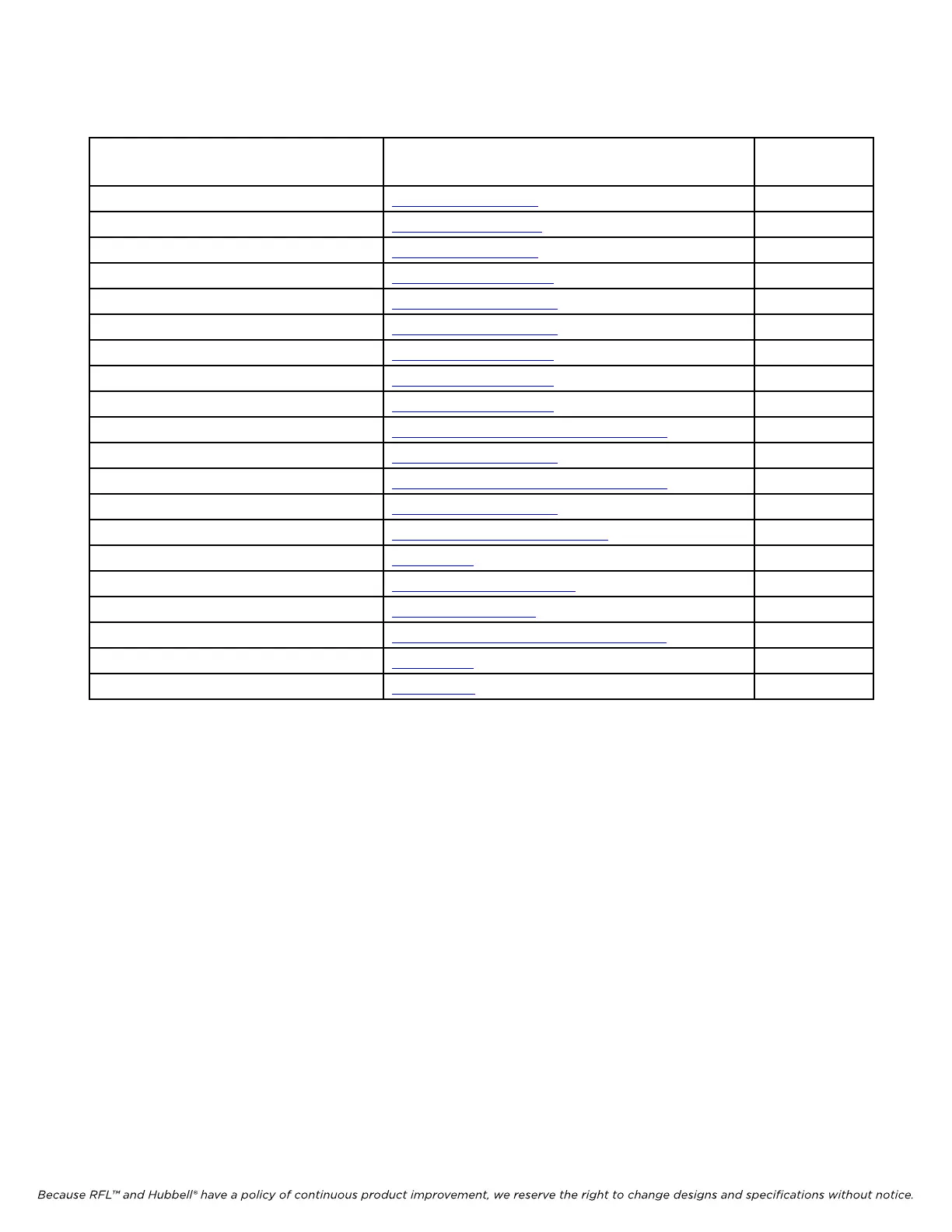
Table 4-2. Controls and indicator information for RFL 9785 system modules
Module Description Controls and Indicators
Information
Refer to
Section:
AM Logic module Table 6-1 & Figure 6-3 6
Transmitter module Table 7-1 & Figure 7-4 7
Power amplifier module Table 8-1 & Figure 8-2 8
Output filter modules Table 10-1 & Figure 10-2 10
Receiver Downshifter module Table 11-1 & Figure 11-3 11
Receiver Detector module Table 12-1 & Figure 12-3 12
SOE/IRIG-B module Table 13-1 & Figure 13-2 13
SOE/IRIG-B I/O module Table 13-3 & Figure 13-5 13
Voice module Table 15-1 & Figure 15-3 15
Checkback module Tables 16-1 & 16-2, & Figures 16-7 & 16-8 16
Power supply module Table 18-2 & Figure 18-2 18
Power supply I/O module Tables 18-4 & 18-5, & Figures 18-6 & 18-8 18
Solid State Input I/O Table 19-2 & Figure 19-3 19
Solid State Input/Output I/O Table 19-4 & Figures 19-7 & 19-8 19
Alarm Relay I/O module Figure 19-11 19
RF Line I/O module Table 19-6 & Figures 19-14 19
Current Limit module Figures 19-16 & 19-17 19
External Power Amp I/O Module Table 19-7 & 19-8 & Figure 19-18 & 19-19 19
Skewed Hybrid I/O module Figure 19-21 19
Checkback alarm chassis Figures 21-1 21