Because RFL™ and Hubbell® have a policy of continuous product improvement, we reserve the right to change designs and specifications without notice.
RFL 9785 RFL Electronics Inc.
September 1, 2006
19-33 (973) 334-3100
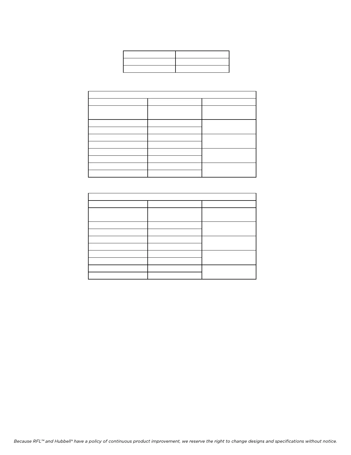
Alarm Input Voltage Selection Jumpers
Input Voltage JP3 and JP4
12V C
48/125V B
Table 19-7. Logic Straps
Logic with straps in position:
JP1-A JP2-A JP5-B
Input Name Input Status at TB9 Output Status at
C12
Fail#1 (TB9-1&-2) 12V or 48/125V 0V (OK)
Fail#2 (TB9-3&-4) 12V or 48/125V
Fail#1 (TB9-1&-2) 0V 5V (FAIL)
Fail#2 (TB9-3&-4) 0V
Fail#1 (TB9-1&-2) 12V or 48/125V 5V (FAIL)
Fail#2 (TB9-3&-4) 0V
Fail#1 (TB9-1&-2) 0V 5V (FAIL)
Fail#2 (TB9-3&-4) 12V or 48/125V
Table 19-8. Logic Straps
Logic with straps in position:
JP1-B JP2-B JP5-B
Input Name Input Status at TB9 Output Status at
C12
Fail#1 (TB9-1&-2) 12V or 48/125V 5V (FAIL)
Fail#2 (TB9-3&-4) 12V or 48/125V
Fail#1 (TB9-1&-2) 0V 0V (OK)
Fail#2 (TB9-3&-4) 0V
Fail#1 (TB9-1&-2) 12V or 48/125V 5V (FAIL)
Fail#2 (TB9-3&-4) 0V
Fail#1 (TB9-1&-2) 0V 5V (FAIL)
Fail#2 (TB9-3&-4) 12V or 48/125V
19.7.2 RECEIVER LINE INTERFACE AND PROIVISION FOR EXTERNAL
METER
The RX Line Interface section provides termination and surge protection for the receive signal. Termination is
selectable via JP101 for 50 ohm, 75 ohm or high impedance. E101 is a 90 volt high- energy spark gap and along
with R105 and CR101 provide maximum surge protection for the 9785 receiver. In addition, connections are
provided for an external power meter.
19.7.3 TX SCALING AND EXTERNAL POWER AMP SECTION
This section provides transmitter signal scaling and output buffering via U1 and associated variable and fixed
resistors. Additionally, provisions for two external power amplifier alarm signals are located on this module. JP3
and JP4 select either 12V or the wide range 48/125V alarm input voltages. See the Alarm Input Voltage
Selection Table for JP3 and JP4 jumper positions. Alarm inputs are isolated via U3 and U4 and any combination
of logic can be selected via jumpers JP1, JP2 and JP5.