Because RFL™ and Hubbell® have a policy of continuous product improvement, we reserve the right to change designs and specifications without notice.
RFL 9785 RFL Electronics Inc.
April 25, 2005
15-6 (973) 334-3100
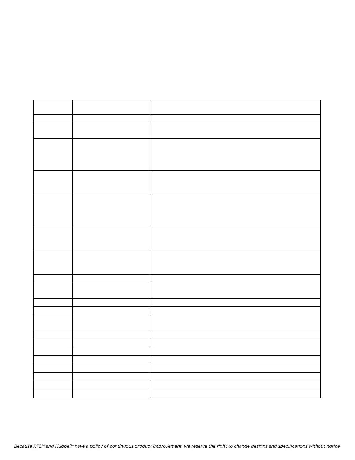
15.4 CONTROLS AND INDICATORS
Figure 15-4 shows the locations of all controls and indicators on the voice module. These controls and
indicators are described in Table 15-1. LEDs DS1 and DS2 are visible with the module installed in the
chassis. All other controls are only accessible when the module is removed from the chassis or is on a
card extender.
Table 15-1. Controls and indicators, RFL9785 Voice Module
Component
Designator
Name/
Description
Function
DS1 LED, Voice enable Lights when the local station is transmitting voice.
DS2 LED, Receiver call Lights when a call is received from the station at the other end of the
protected line.
J1 Jumper, normal/test Controls the AGC circuit as follows:
NORM: AGC circuit enabled
TEST: AGC circuit disabled. Used during module alignment only.
For proper module operation, J1 must be in the NORM position.
J2 Jumper, AGC in/out Controls the AGC function as follows:
IN: AGC function enabled
OUT: AGC function disabled.
J3 Jumper, side tone in/out Controls the sidetone (voice) fed back from the handset microphone
to the handset headphone as follows:
IN: Sidetone enabled
OUT: Sidetone disabled.
J4 Jumper, alarm cutoff
internal/external
Controls the location of the Alarm Cutoff contacts as follows:
INT: Contacts located in handset plug.
EXT: Contacts located at 9785 rear panel terminal block.
J5 Jumper, enable /disable Controls Audible alarm as follows:
ENABLE: Audible alarm enabled
DISABLE: Audible alarm disabled.
R7 Potentiometer Input level adjust
R63 Potentiometer Controls the amount of signal sent to the transmitter module. This
controls the % modulation to be applied to the carrier.
R71 Potentiometer Audio level adjust
R125 Potentiometer Tone adjust
SP1 Audible warning device An audible tone is heard when a call is received from the station at
the other end of the protected line.
TP1 Test point, Common Ground reference
TP2 Test point, Level Monitoring point for input signal level
TP3 Test point, AGC IN Monitoring point for input of AGC circuit
TP4 Test point, AGC OUT Monitoring point for output of AGC circuit
TP5 Test point, MOD LEV Monitoring point for output of voice detector
TP6 Test point, AUD OUT Monitoring point for audio output signal
TP7 Test point, TONE Monitoring point for call tone
TP8 Test point, VOICE DETECT Monitoring point for local voice signal