Because RFL™ and Hubbell® have a policy of continuous product improvement, we reserve the right to change designs and specifications without notice.
19.8.3 CONTROLS AND INDICATORS
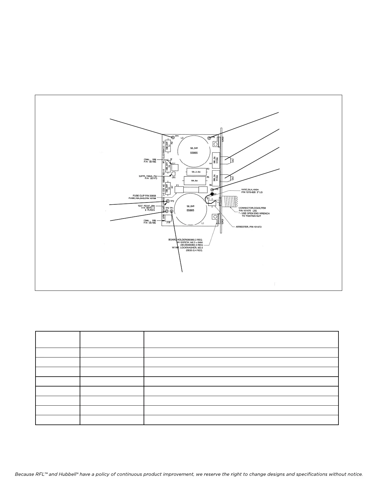
Figure 19-21 shows the location of all controls and indicators on the Skewed Hybrid module. These
controls and indicators are described in Table 19-9. Only R4 and R6 are accessible with the Skewed
Hybrid Module installed in the chassis. All others are accessible only when the module is removed
from the chassis.
TP4
TP3
TP2
TP6
R4
R6
TP5
TP1
Figure 19-21. Controls and indicators, RFL 9785 Skewed Hybrid I/O
Table 19-9. Controls and Indicators, RFL 9785 Skewed Hybrid I/O.
Component
Designator
Name/Description Function
R6 Potentiometer Coarse adjustment for balancing network
R4 Potentiometer Fine adjustment for balancing network
TP1 Test point Send High (orange)
TP2 Test point Send Low (orange)
TP3 Test point Receive High (orange)
TP4 Test point Receive low (orange)
TP5 Test point Line High (orange)
TP6 Test point Line Low (orange)
RFL 9785 RFL Electronics Inc.
September 1, 2006
19-38 (973) 334-3100