Because RFL™ and Hubbell® have a policy of continuous product improvement, we reserve the right to change designs and specifications without notice.
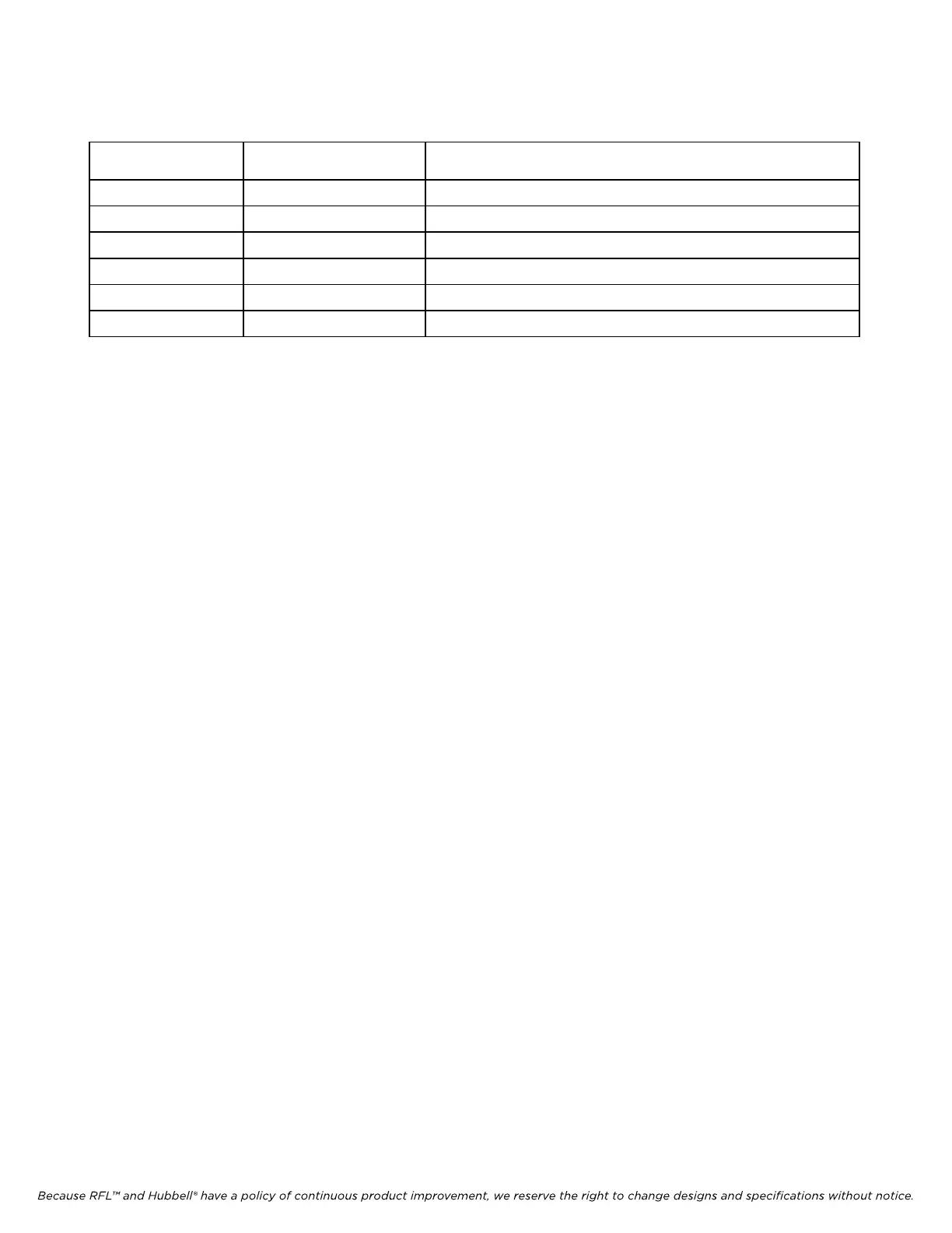
Table 8-1. Controls and indicators, RFL 9785 Power Amplifier module
Component
Designator
Name/Description Function
R2 Potentiometer Gain adjustment
R10 Potentiometer Threshold voltage adjustment
R16 Potentiometer Output impedance adjustment
TP1 Test point Input signal test point
TP2 Test point Operational amplifier (U1) output
TP3 Test point Output signal test point
8.4.1 AMPLIFIER GAIN
The amplifier gain can be adjusted with Potentiometer R2. This adjustment can be used to vary the
output signal level, and thus power. The “Transmit Amplitude” adjustment on the Transmitter Module
can also be used to vary the output level.
8.4.2 OUTPUT IMPEDANCE
The Power Amplifier Module has provisions for adjusting the unit’s output impedance to compensate
for variations in actual field installations. This should only require setting upon initial installation, or
following system changes that impact the impedance the 9785 is driving.
To match the impedance proceed as follows (with the system off-line):
1. Set the unit to transmit a 3 W signal (1 W would also work). Do not set the unit for a 10 W
transmit level.
2. Remove the load from the output of the 9785 and measure the output signal voltage.
3. Connect the (actual) load to the 9785 and adjust potentiometer R16 (IMP ADJ) to obtain one-
half of the unloaded output signal level.
8.4.3 LOW-LEVEL ALARM THRESHOLD
The low-level alarm threshold is set using potentiometer R10.
RFL 9785 RFL Electronics Inc.
September 1, 2006 8-5 (973) 334-3100