Because RFL™ and Hubbell® have a policy of continuous product improvement, we reserve the right to change designs and specifications without notice.
RFL 9785
April 25, 2005
15-12 (973) 334-3100
RFL Electronics Inc.
15.5.2 CONTROLS AND INDICATORS CONTROLS AND INDICATORS
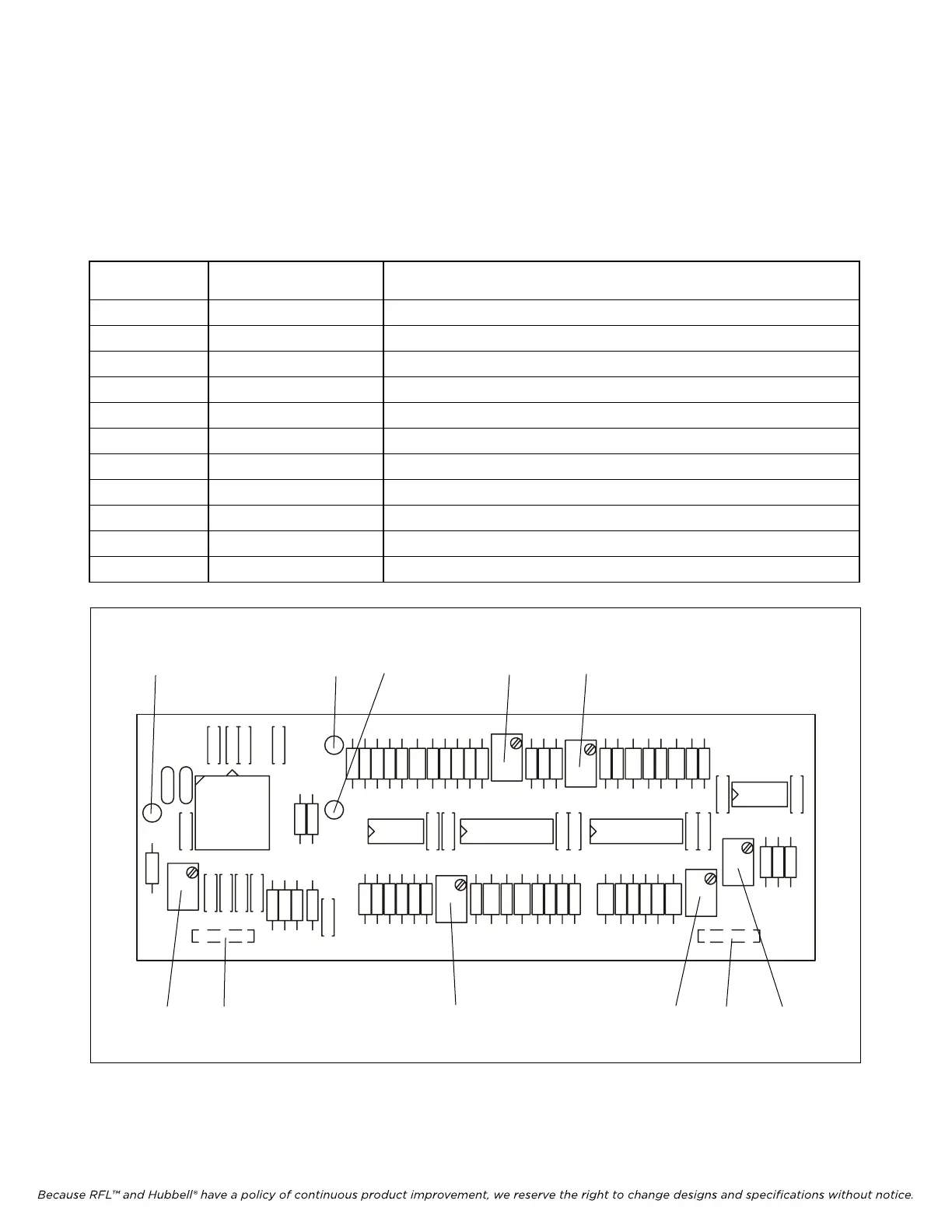
Figure 15-7 shows the locations of all controls and indicators on the voice filter. These controls and
indicators are described in Table 15-2. All controls and indicators are only accessible when the voice
module is removed from the chassis or is on a card extender.
Figure 15-7 shows the locations of all controls and indicators on the voice filter. These controls and
indicators are described in Table 15-2. All controls and indicators are only accessible when the voice
module is removed from the chassis or is on a card extender.
Table 15-2. Controls and indicators, RFL 9785 Voice Filter Table 15-2. Controls and indicators, RFL 9785 Voice Filter
Component Component
Designator Designator
Name/ Name/
Description Description
Function Function
P1 Connector plug Mates with J1 on Receiver Detector module (voice filter input)
P2 Connector plug Mates with J2 on Receiver Detector module (voice filter output)
R1 Potentiometer Not used on RFL 9785 voice filter
R19 Potentiometer Upper notch adjustment (for factory adjustment only)
R25 Potentiometer Passband balance adjust (for factory adjustment only)
R33 Potentiometer Lower notch adjustment (for factory adjustment only)
R39 Potentiometer Passband balance adjust (for factory adjustment only)
R43 Potentiometer Output level adjust
TP1 Test point Not used on RFL 9785 voice filter
TP2 Test point Not used on RFL 9785 voice filter
TP3 Test point Buffered input signal
R1
TP2
U1 C6
C1
R2
R44
U2
U3
R19
R25
R33TP1
TP3
C4
C5
C7
C9
C8
C3
C11
C10
C12
C17
C16
P1
C22
C23
C24
C25
C26
C30
C19
C32
C13
C14
C15
C18
C21
R3 R4
R7
R8 R9
R10
R11
R12
R13 R14
R15 R16
R18
R17
R21
R20
R22
R23
R24
R27
R28
R26
R31
R32
R37
R36
U4
C20
C36
C37
1999 RFL ELECTRONICS INC
U5
R39
R43
C29
C31
C27
C28
C35
C34
C33
R34R30
R29
R35
R38
R41
R40
R42
P2
106583 REV B
FILTER
97 VOICE
1
1
Figure 15-7. Controls and indicators, and component locator drawing, RFL 9785 Voice Filter
TP1 TP3 TP2 R19 R33
R1 P1 R26 R39 P2 R43