Because RFL™ and Hubbell® have a policy of continuous product improvement, we reserve the right to change designs and specifications without notice.
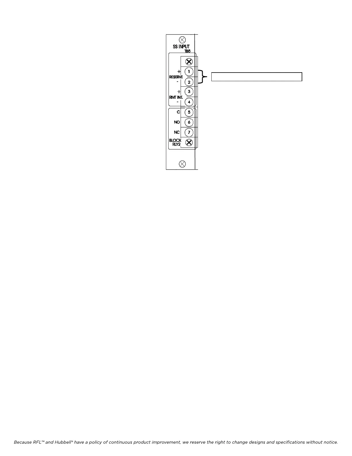
“RESERVE” keying inputs
Figure 22-11. Location of “RESERVE” Keying Inputs
c) Adjust R2 on the Power Amp to obtain a reading of 14.14Vrms (36dBm).
d) Re-install J1 into previously noted A, B, or C position on the Output Filter Module. With the
FSVM leads on the Output Filter Module TP1 (Brown – “COM”) and TP3 (White – “IN”),
adjust R16 on the Power Amp to obtain 7.07Vrms (30dBm), which is 50% of the previously
measured open-circuit (Output Filter Module Jumper J1 removed) voltage.
The Transmit carrier output level should now be aligned for proper operation.
9) Disconnect the dummy load from the carrier output connector and reconnect the coax from the
carrier set to the line tuner.
10) Adjust Line Tuning Units for minimum reflected power according to the manufacturer’s
recommendations.
a) A Reflected Power reading of =<4% or 14dB (forward & reverse) should be achieved for
optimum performance.
RFL 9785 RFL Electronics Inc.
March 1, 2013 22-12 (973) 334-3100