Because RFL™ and Hubbell® have a policy of continuous product improvement, we reserve the right to change designs and specifications without notice.
9.5 MODULE PLACEMENT IN THE RF CHASSIS (100W SYSTEMS)
100 Watt systems will comprise of a 50 Watt system in a 3U high chassis, and will have an additional
50 Watt system in a 3U high chassis mounted above it as shown in Figure 9-1. There must be a
minimum 1U space between the lower 3U chassis and the upper 3U chassis for convection cooling.
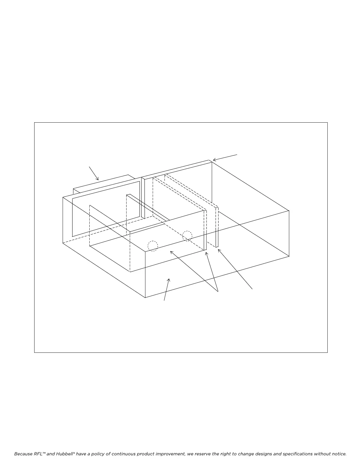
The 3U chassis will contain a 50W Power Amplifier, a Power Amp Power Supply, a Tx Filter, an
External Amp Connection Board and a Motherboard. The External Amp Connection Board has no
components and consists only of a PC board and a motherboard connector. A view of the additional
3U chassis is shown in Figure 9-17.
EXTERNAL
AMP
CONNECTOR
BOARD
TX
FILTER
POWER AMP
POWER SUPPLY
MOTHER
BOARD
50W POWER AMP
(Mounted on front door,
not shown for clarity)
Figure 9-17. Module placement in auxiliary 3U RF Chassis for 100W Systems (Top View)
RFL 9785 RFL Electronics Inc.
May 16, 2011 9-23 (973) 334-3100
 Loading...