Because RFL™ and Hubbell® have a policy of continuous product improvement, we reserve the right to change designs and specifications without notice.
RFL 9785 RFL Electronics Inc.
June 18, 2009 2-5 (973) 334-3100
2.5.3 GENERAL
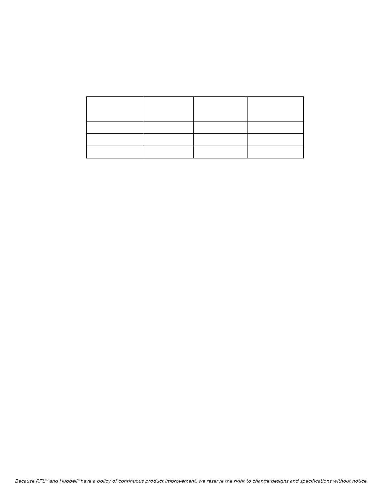
Channel Spacings And Delay Times: See Table 2-1.
Table 2-1. Minimum permissible channel spacings and delays times,
RFL 9785 Programmable ON/OFF Powerline Carrier System
Nominal
Bandwidth
Delay Channel
Spacing
w/voice
Channel
Spacing
w/o Voice
500 Hz 5 ms 4 KHz 1 KHz
1000 Hz 3 ms 4 kHz 2 kHz
1500 Hz 1.5 ms 4 kHz 3 kHz
Alarms: There are two standard alarms: transmitter output level and power supply failure.
Checkback Outputs:
Checkback test in progress
Ckeckback test fail
Interface Dielectric Strength: All input and output circuits are isolated from ground and from all
other circuits. Breakdown is 1500 Vrms @ 50/60 Hz, 2500 Vdc, and 2500 Vrms @ 1.5 MHz, in
accordance with IEEE Surge Withstand Capability Specification 472-1978 (ANSI C.37.90-1978).
The RFL 9785 also meets the requirements of ANSI-IEEE Fast Transient Specification C.37.90.1-
1988.
Input Power Requirements:
Voltage Range:
48-Vdc Systems: 40 Vdc to 58 Vdc.
125-Vdc Systems: 103 Vdc to 155 Vdc.
250-Vdc Systems: 200 Vdc to 300 Vdc.
Power Consumption: 85 watts max.
Operating Temperature: -20
o
C to +60
o
C (-4
o
F to +140
o
F).
Dimensions:
Height: 10.5 inches (267 mm).
Depth: 13.0 inches (330 mm).
Overall Width: 19 inches (483 mm).
Weight: Less than 30 lbs (13.6 kg).
2.6 TERMINAL CONFIGURATION
The RFL 9785 is housed in a single 3U high, rack mounted chassis. Table 2-2 shows general
information about the available modules for the RFL 9785. Figure 2-2 shows a typical block diagram
of an RFL 9785 chassis. A summary of each module is included in paragraphs 2.7.1 through 2.7.12.
Detailed descriptions of the modules can be found in Sections 6 through 19.